However, typical systems create more tension than is required to lock the stitch.
When the take up lever moves back up, thread is pulled from the hook and
bobbin, resulting in the extra thread tension.
The increased amount of material required for the backing increases cost, compared to stitching a garment using no backing.
Additionally, the use of backing material also increases the labor required to stitch a pattern into a garment, compared to stitching a garment with no backing.
In addition to necessitating the need for backing material as described above, the extra thread tension created by the mechanical apparatuses, which pull thread from the spools to the needle assemblies, may lead to thread breaks, which can interrupt the stitching process.
If the embroidery
machine has multiple stitching heads, and a thread breaks on one of the stitching heads, it may be more difficult to correct the thread break.
Thus, when a break occurs in such a
system, additional steps must be taken to “catch up” the sewing head which had the thread break.
Additionally, in typical machines which employ mechanical apparatuses to pull thread from the spool, the amount of thread pulled from the spool for each stitch may not be consistent, due to geometrical variations which occur from stitch to stitch.
This inconsistent amount of thread pulled from the spools results in differing thread tension from stitch to stitch, and may result in inconsistent sew-outs.
Inconsistent sew-outs may result in a completed pattern that has less uniformity from stitch to stitch, and may thus reduce the aesthetic appeal of the stitched pattern.
As mentioned above, embroidery systems may encounter thread breaks, where the upper thread being stitched from the spool and needle
assembly may break.
Additionally, a break may occur in the thread being used to lock the stitch using the
bobbin and hook
assembly, known as a lower thread break.
Thread may break for a number of reasons, including tension in the sewing process, incorrect feeding into the
system from the thread spool or
bobbin, and binding in the mechanical apparatuses which pull the thread into the needle or hook
assembly, to name a few.
When the
control electronics receive a
signal that the upper thread is not moving as expected, this indicates a problem with the sewing process such as a thread break, and the
control electronics act to halt the stitching operations of the embroidery
system.
While current sensors for detecting thread breaks are adequate for detecting such breaks, they commonly have problems associated with them.
In particular, underthread detectors can be problematic during operations of an embroidery system.
Because of their location beneath the garment being stitched, it is common for debris to accumulate in or around the underthread
detector.
This may result in the underthread
detector malfunctioning, and giving false readings of thread breaks or not detecting a thread break.
In addition to debris,
lubricant from the mechanical apparatuses may also accumulate in and around the underthread
detector, resulting in the sensor associated with the underthread detector malfunctioning, which can also result in the underthread detector having to be cleaned or replaced.
In addition to the inadequacies of current underthread detectors, upper thread break sensors also have several problems commonly associated with them.
One such problem is the location of the sensor.
If the presser foot does not contact the garment surface, the garment may lift from the needle plate when the needle lifts through the garment, thus creating the potential for inconsistent sew-outs.
Alternatively, if the garment is made of a relatively thick fabric, the presser foot may strike the garment with a relatively high force, creating a relatively loud audible sound, and causing mechanical stress in the presser foot, reducing its life-time.
Low noise operation is desirable especially when several embroidery machines are located in the same room, because additional
noise may result in difficulty for people around the machines hearing other people or audible alarms.
As a result, many times the presser foot is improperly adjusted, or not adjusted at all.
The presser foot may be improperly adjusted because an operator may make a first adjustment, and not make any additional adjustments to further fine tune the presser foot height, due to the burden of the adjustment process.
In certain cases, the presser foot may not be adjusted at all, due to the burden of the adjustment process.
If the needle hits the hoop, it can damage the needle and result in the embroidery
machine being inoperable and needing repair.
This results in
downtime for the
machine, as well as the cost of the replacement parts and labor to install the replacement parts.
However, occasionally the hoop size entered into the
software is not correct or the position of the pattern relative to the hoop is offset.
In such a case, if the hoop actually placed onto the embroidery machine is smaller than the hoop that the
control system thinks is there or if the pattern is offset, the needle may contact the hoop and cause damage.
One such drawback for using such a procedure to verify that a needle will not hit the hoop is that often the needle is pulled down far enough that, if the pattern does overlap the hoop, the hoop will contact the needle during the tracing procedure described above.
Thus, if an incorrect hoop is on the embroidery machine, a needle may still be damaged even using the visual
verification described above.
Also, if a needle is pulled down too far, the garment may be damaged.
Additionally, there are safety concerns with the procedures described above.
Namely, an operator may be injured in the process of pulling a needle down from the needle case, or pushing the needle back into the needle case.
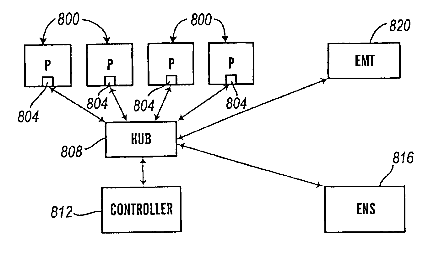
Furthermore, as mentioned above, thread breaks often require the stoppage of all of the heads in a stitching machine.
Additionally, these type of machines generally have a fixed number of heads, and if additional capacity is desired, an entire new machine must be purchased, often at considerable expense.

