Apparatus for cooling material to be printed and printing units at sheet fed printing machines with cooled compressed air

Inactive Publication Date: 2006-01-10
KOENIG & BAUER AG
View PDF40 Cites 21 Cited by
  • Summary
  • Abstract
  • Description
  • Claims
  • Application Information

AI Technical Summary

Benefits of technology

[0009]It is an object of the present invention to provide an apparatus which requires little space and is able to coo

Problems solved by technology

The amount of heat, which is emitted by convection or radiation and not used for the drying process, is regarded as a disturbance for the printing process and the sheet delivery (adversely affects the printing in the subsequent printing machinery, excessively increases the stack temperature, damages thermally sensitive material to be printed) and, moreover, adversely affects the mode of functioning of adjacent machine elements in the event that these are overheated impermissibly.
However, it does not cool sheet-guiding surfaces heated by radiation.
However, the cooling effect is limited only to the baffles and does not extend to the

Method used


Image

  • Apparatus for cooling material to be printed and printing units at sheet fed printing machines with cooled compressed air
  • Apparatus for cooling material to be printed and printing units at sheet fed printing machines with cooled compressed air
  • Apparatus for cooling material to be printed and printing units at sheet fed printing machines with cooled compressed air

Examples


Embodiment Construction

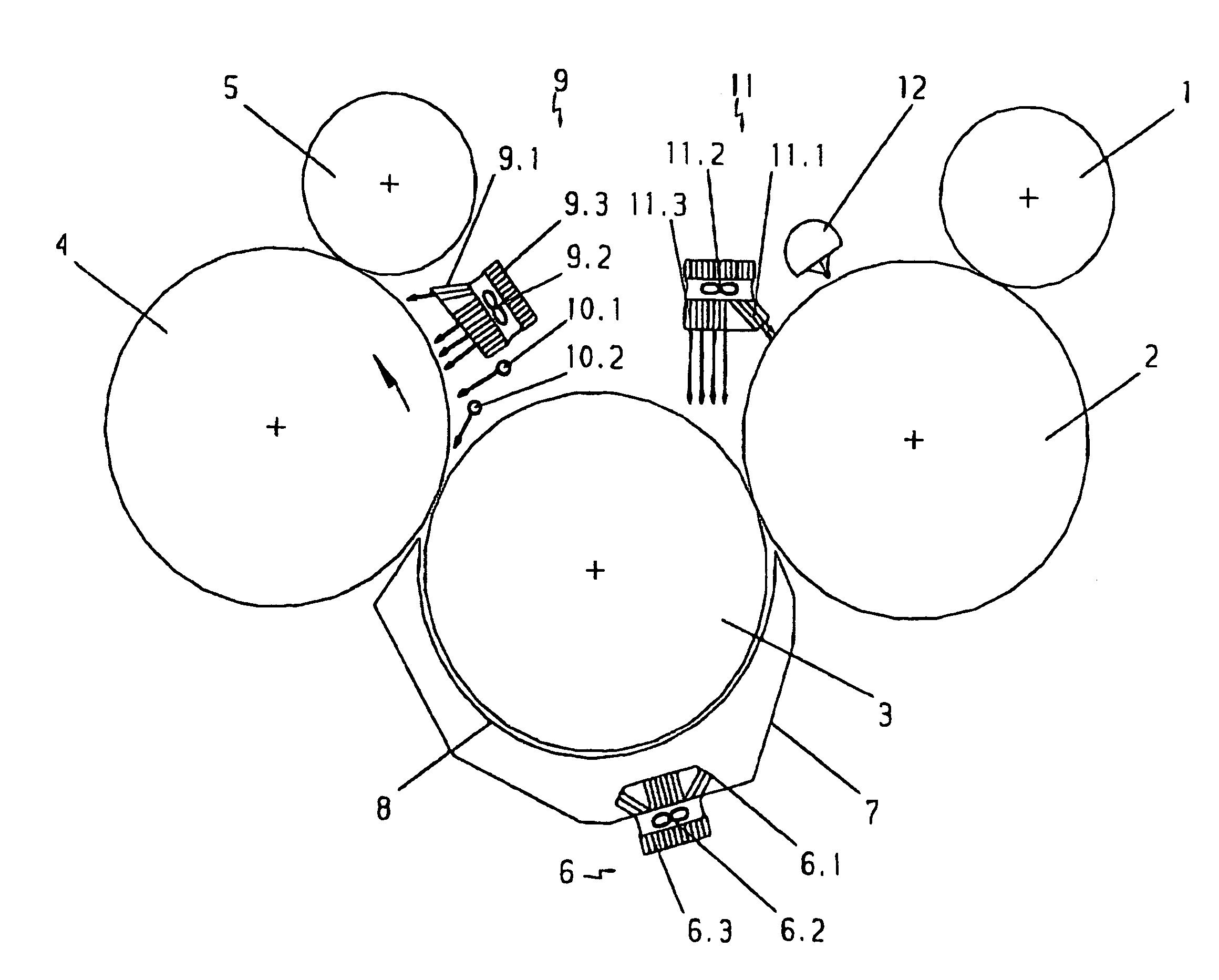
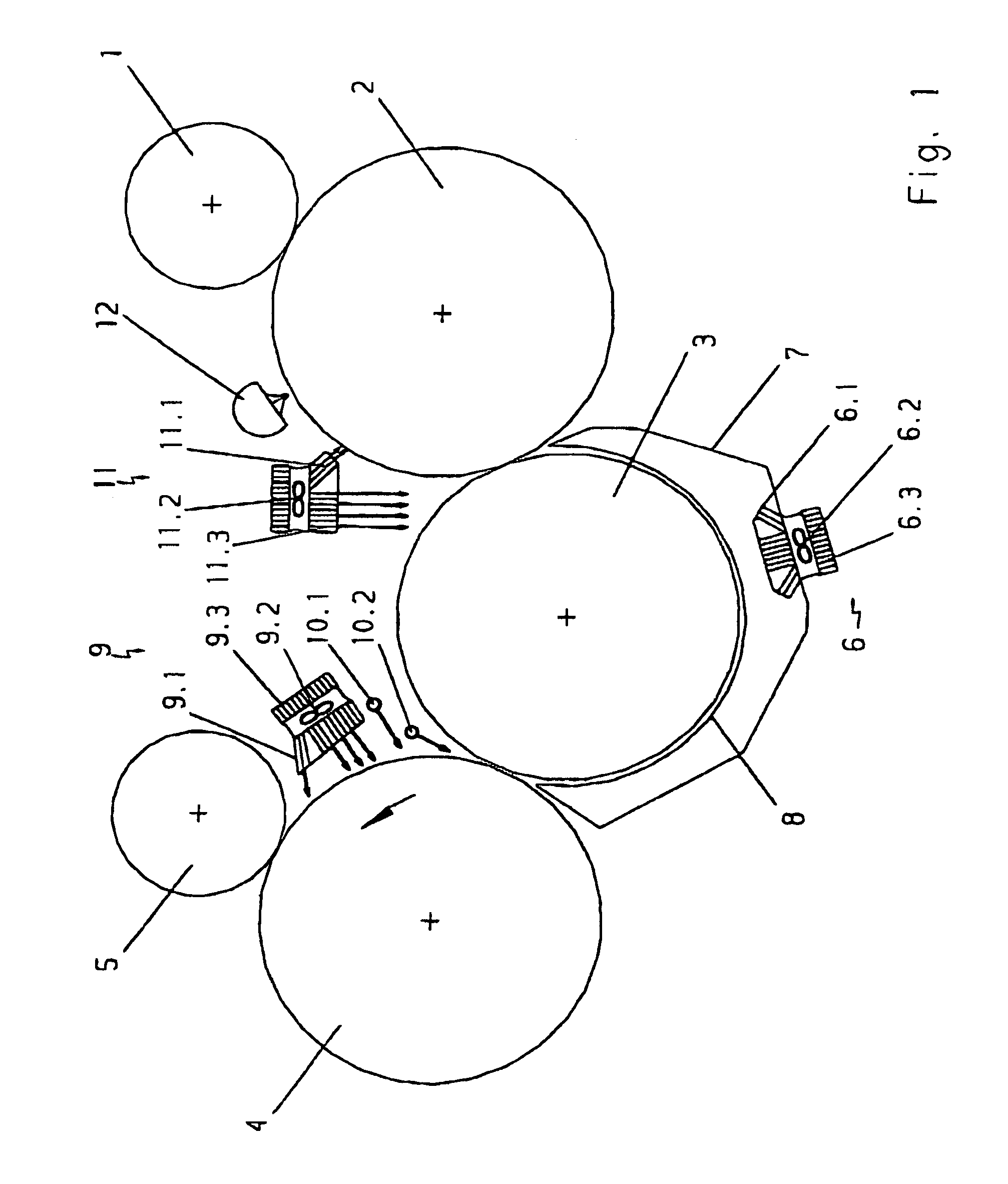
[0026]In diagrammatic representation, FIG. 1 shows the sheet-guiding cylinders of two printing or varnishing units of a rotary sheet printing machine in in-line construction, between which there is a transfer drum 3. Of the printing units which are located upstream and downstream in the moving direction of the sheets, in each case only the printing cylinders 2, 4 and the rubber blanket cylinders 1, 5 interacting therewith, are shown. Depending upon the printing job and the machine configuration, pneumatic sheet-guiding devices, of which sheet-guiding devices 7, 9, 10, 11 are shown by way of example, are present along the moving path of the sheet.

[0027]Below the transfer drum 3, there is a well-known blast box 7, which prevents smearing of the printed sheet at an air cushion plate 8. Before the printing zone 4, 5 of the downstream printing unit, the sheet is placed smoothly against the printing cylinder 4 with the help of a blast box 9 and, depending on the thickness of the material ...


PUM


Abstract

The present invention relates to an apparatus for cooling material to be printed and printing machine elements at sheet-fed rotary printing machines by means of cooled compressed air. It is an object of the present invention to provide an apparatus which requires little space, is able to cool effectively the material to be printed as well as the machine elements, which are undesirably heated by the dryers. Pursuant to the present invention, this objective is accomplished by providing an apparatus wherein cooled, compressed air is supplied over one or more sheet-guiding devices for guiding the sheets pneumatically along the sheet-guiding path, and a cooling device is disposed in the cross section of flow of the compressed air or the sheet-guiding device.

Description

FIELD OF THE INVENTION[0001]The present invention relates to an apparatus for cooling materials to be printed and printing machine elements at sheet-fed rotary printing machines by means of cooled compressed air.BACKGROUND OF THE INVENTION[0002]It is generally known that, for supporting the drying and curing processes of printing inks and especially of varnishes, dryers may be disposed at or between printing units and in the delivery area. At the same time, large amounts of primary (infrared dryer) or secondary (UV dryer) heat are delivered to the materials to be printed and to the printing machine assembly adjacent to the dryers. The amount of heat, which is emitted by convection or radiation and not used for the drying process, is regarded as a disturbance for the printing process and the sheet delivery (adversely affects the printing in the subsequent printing machinery, excessively increases the stack temperature, damages thermally sensitive material to be printed) and, moreover...

Claims


Application Information

Patent Timeline
IPC IPC(8): B41F23/04B41F25/00
CPCB41F25/00B41F23/0483
Inventor KOCH, MICHAELSTEINBORN, TILO
Owner KOENIG & BAUER AG
Why Eureka
Try Eureka