Supply connection device for a fluid pressure system

a fluid pressure system and connection device technology, applied in the direction of mechanical equipment, pipe elements, couplings, etc., can solve the problems of inability to meet production requirements, inconvenient operation, and difficulty for operators to connect the device in its locking position, so as to avoid accidental disconnection, avoid damage to the working surface of the body, and avoid the effect of accidental disconnection

Inactive Publication Date: 2006-01-10
VALEO EMBRAYAGES SAS
View PDF16 Cites 47 Cited by
  • Summary
  • Abstract
  • Description
  • Claims
  • Application Information

AI Technical Summary

Benefits of technology

[0035]Preferably, the locking device for the locking means is repositioned for elastic deformation in the locking position once the operator ceases to exert a releasing force on the locking means, so that the device is more reliable.
[0036]According to the invention, the releasing force is a small pushing force, such as thumb pressure by the operator, which must be applied on a connecting portion of the locking means to cause the elastic deformation to take place. By applying a pushing force, the operator is under ergonomic working conditions without any risk of accidental disconnection, and it is no longer necessary to provide means similar to the safety notches in the document DE-A-19603506. Another result is simple mounting of the hairpin similar to that which was known from FR-A-2 736 136, in the field of hydraulic coupling devices.
[0037]Preferably, the friction effects of the locking means on the body take place on external surfaces of the body, so that no damage to the working surfaces of the body is likely over time due to repeated manoeuvres of the locking means, and thus for example the internal bore which participates in the guiding and sealing functions is preserved.

Problems solved by technology

It is not easy for the operator to connect the device in its locking position, because it is necessary that the first or rear groove shall be in axial coincidence with the locking means.
Now since there is no way that the operator can control this good positioning by eye, it is necessary to proceed by trial and error, which is not satisfactory for various reasons.
Among these reasons may be mentioned the time which can be necessary for the operator to position the connector in its purge position, and this is incompatible with production requirements, particularly in the case where these assembly operations are carried out on production lines for motor vehicles in which each operation is scrupulously timed.
These problems do of course occur as much for an operator during the first time the operation is carried out as later on during maintenance operations on the vehicle.
Apart from the fact that the second set of operations on the device has the same disadvantages as before, it gives rise above all to an additional safety problem.
In default of this, retention of the connector is not guaranteed, and under the action of the fluid pressure, there is a danger of the connector being expelled violently out of the feed inlet body.
This displacement of the stop fingers on the ramps is limited by safety notches against which the fingers come into abutment, and it is therefore impossible for the finger to be removed accidentally while the pulling release force is being exerted on the latter.
However, the initial fitting of the hairpin necessitates an additional intermediate member and can only be carried out in an axial, and not a radial, direction.
In addition, the force exerted on the connecting portion between the two branches of the hairpin, for the purpose of unlocking it, is a tractive force which is not natural for an operator, and which is in particular difficult to maintain during the unlocking operation.

Method used


Image

  • Supply connection device for a fluid pressure system
  • Supply connection device for a fluid pressure system
  • Supply connection device for a fluid pressure system

Examples


Embodiment Construction

[0049]In the following description, in order to assist understanding, we will use, without limitation, the expressions vertical, horizontal, front, rear, left, right etc. with reference to the drawings and in accordance with the definitions given in the description.

[0050]In the description, those elements which are identical, similar or analogous to each other will be designated by the same reference signs.

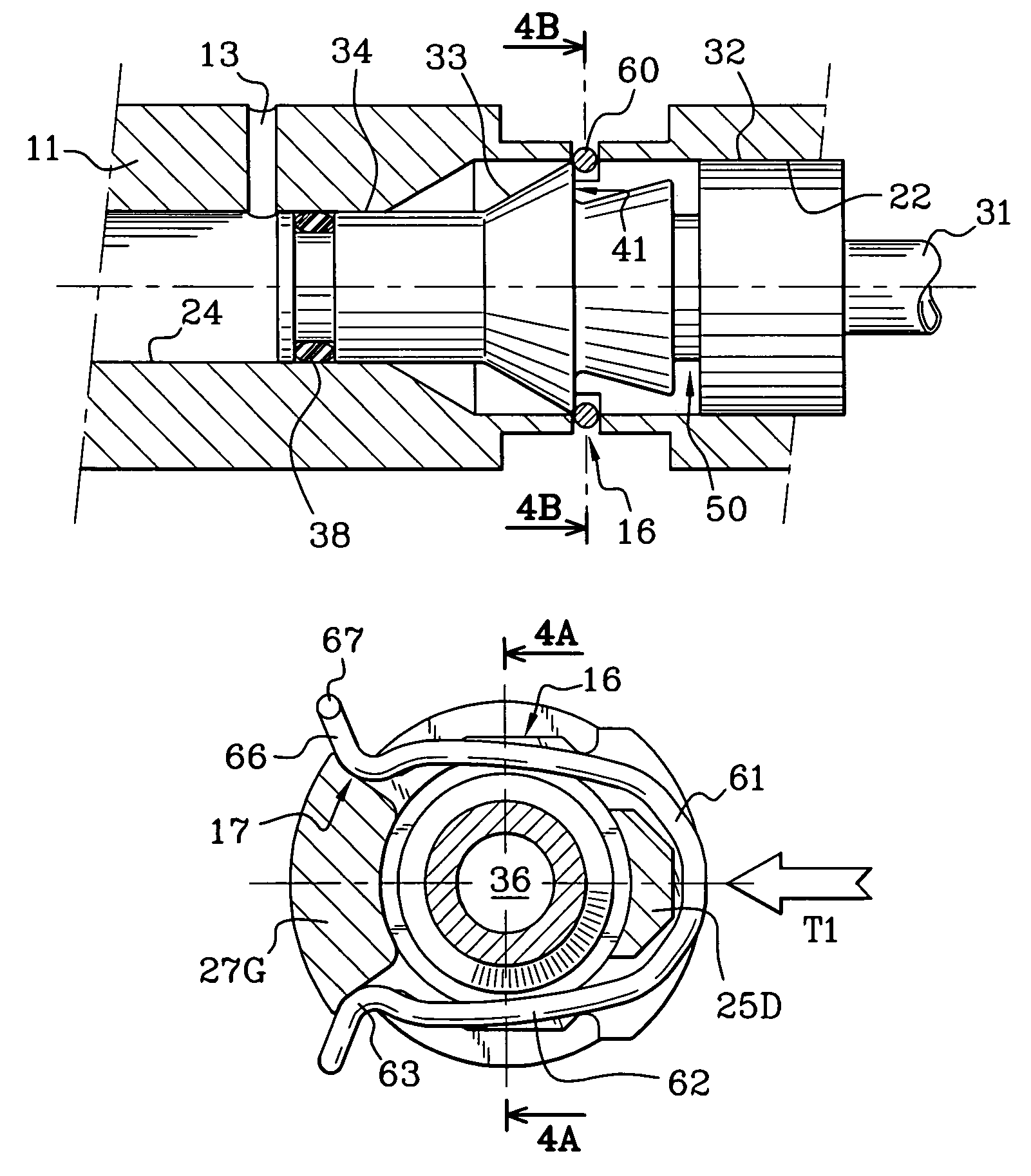
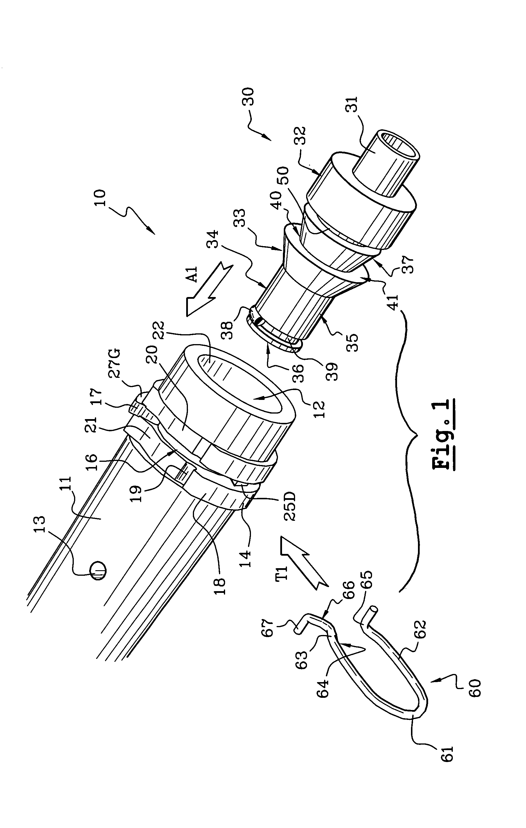
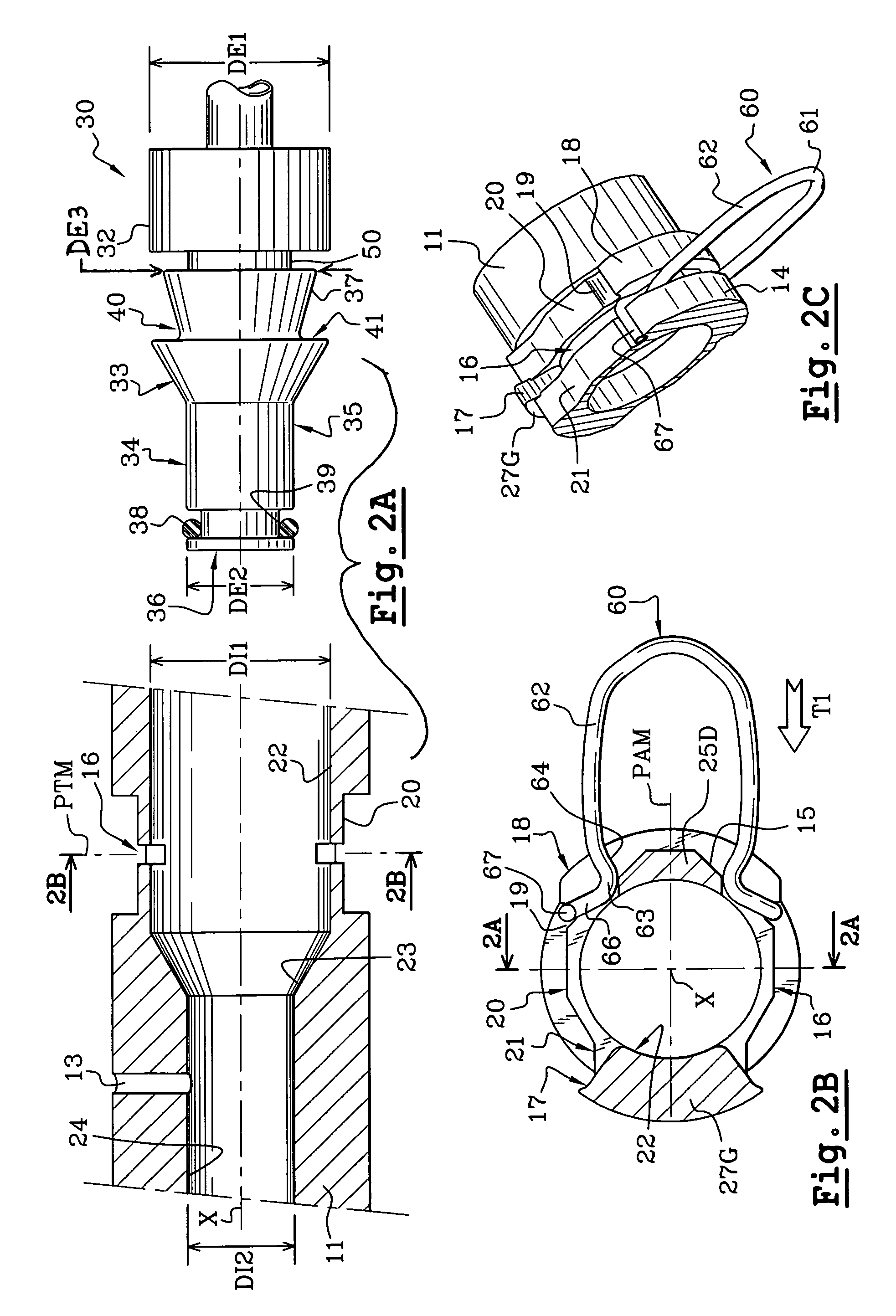
[0051]The device 10, for connecting a feed line for a pressure fluid system, which is shown in FIGS. 1 to 5, consists essentially of a front body 11 of a feed inlet 12, which in this example is substantially tubular with an axis X, and which is able to be fixed with respect to a hydraulic member such as a receiver (not shown), together with a rear connector 30 which is arranged to be fixed to the end of a feed pipe (not shown).

[0052]We choose to describe here the device 10 in the case where the connector 30 is considered to be movable with respect to the feed inlet 12, but, withou...


PUM


Abstract

A supply connection device for a fluid pressure system, the connection includes a head designed to be axially received in a body of a supply intake, and the connection is capable of being locked in a front position axially engaged in the supply intake body by a locking mechanism, which includes a globally symmetrical U-shaped pin with two transverse locking branches. The connection is unlocked from the body, for axially releasing, at least partly, rearward the connection outside the body, by elastic deformation of the locking mechanism which results from the co-operation between at least a part of the locking branches and at least a part of the body under the action of a releasing force exerted on the locking mechanism along a transverse direction. The elastic deformation is obtained by exerting a releasing force thrusting a connecting section of the two braches of the pin.

Description

BACKGROUND OF THE INVENTION[0001]1. Field of the Invention[0002]This invention relates to a device for connecting the feed for a fluid pressure system.[0003]More particularly, the invention relates to a device for connecting the feed for a pressure fluid system, of the type in which a connector comprises a head adapted to be received axially in a body of a feed inlet, and of the type in which the connector is adapted to be locked in position before being engaged axially in the feed inlet body by locking means.[0004]2. Description of the Related Art[0005]It is known to make use of connectors of this type, also referred to as plug-in connectors, in order to make the connection in a feed pipe on the inlet of a hydraulic member in a simple and inexpensive way.[0006]Such a coupling device for a feed of a fluid pressure system is for example known from the document FR-A-2 736 136.[0007]That document describes more particularly a device of the type in which a connector is adapted to be hel...

Claims


Application Information

Patent Timeline
Patent Type & Authority Patents(United States)
IPC IPC(8): F16L37/00F16L37/14
CPCF16L37/144F16L37/088F16L37/0885F16L37/14
Inventor RAUTUREAU, STEPHANE
Owner VALEO EMBRAYAGES SAS
Why Eureka
Try Eureka