Windmill blade and apparatus for generating power using the blade

a technology of windmill blades and blades, which is applied in the direction of rotors, marine propulsion, and vessels, can solve the problems of difficult blade angle adjustment, inability to cope with variation in wind force, and the above mentioned conventional wind power generation devices that generate little wind power, etc., and achieve the effect of improving the efficiency of utilizing wind power pressur

Inactive Publication Date: 2006-01-10
JANG KEUN SUK
View PDF8 Cites 72 Cited by
  • Summary
  • Abstract
  • Description
  • Claims
  • Application Information

AI Technical Summary

Benefits of technology

[0010]Therefore, the present invention has been made in view of the above mentioned problems involved with the conventional device, and an object of the invention is to provide a windmill blade capable of varying the wind pressure receiving area thereof depending on a variation in the force of wind, thereby achieving an enhancement in the efficiency of utilizing the pressure of wind without being damaged by strong force of wind.

Problems solved by technology

For this reason, they were often damaged by a strong wind force.
However, all of these conventional windmill blades have a structural drawback in that they cannot cope with a variation in wind force.
However, where the wind force is strong, it is difficult to adjust the angle of the blade because resistance to the wind force increases.
However, the above mentioned conventional wind power generating device generates little wind power because it uses the single windmill blade to generate the wind power.
Furthermore, there is no means for changing the direction of the windmill blade depending on a variation in the direction of wind.
For this reason, the conventional wind power generating device exhibits a low efficiency of generating wind power.
As a result, there is a problem in that it is impossible to obtain a large quantity of power from such a conventional device.

Method used


Image

  • Windmill blade and apparatus for generating power using the blade
  • Windmill blade and apparatus for generating power using the blade
  • Windmill blade and apparatus for generating power using the blade

Examples


Embodiment Construction

[0056]Now, preferred embodiments of the present invention will be described in detail with reference to the annexed drawings.

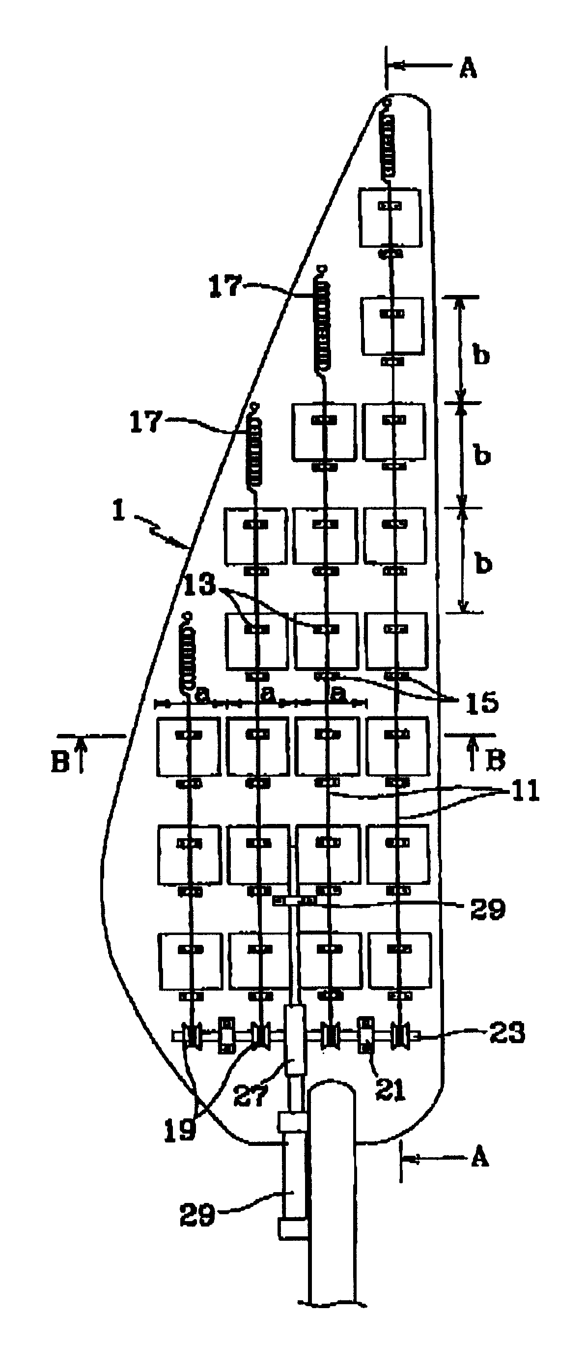
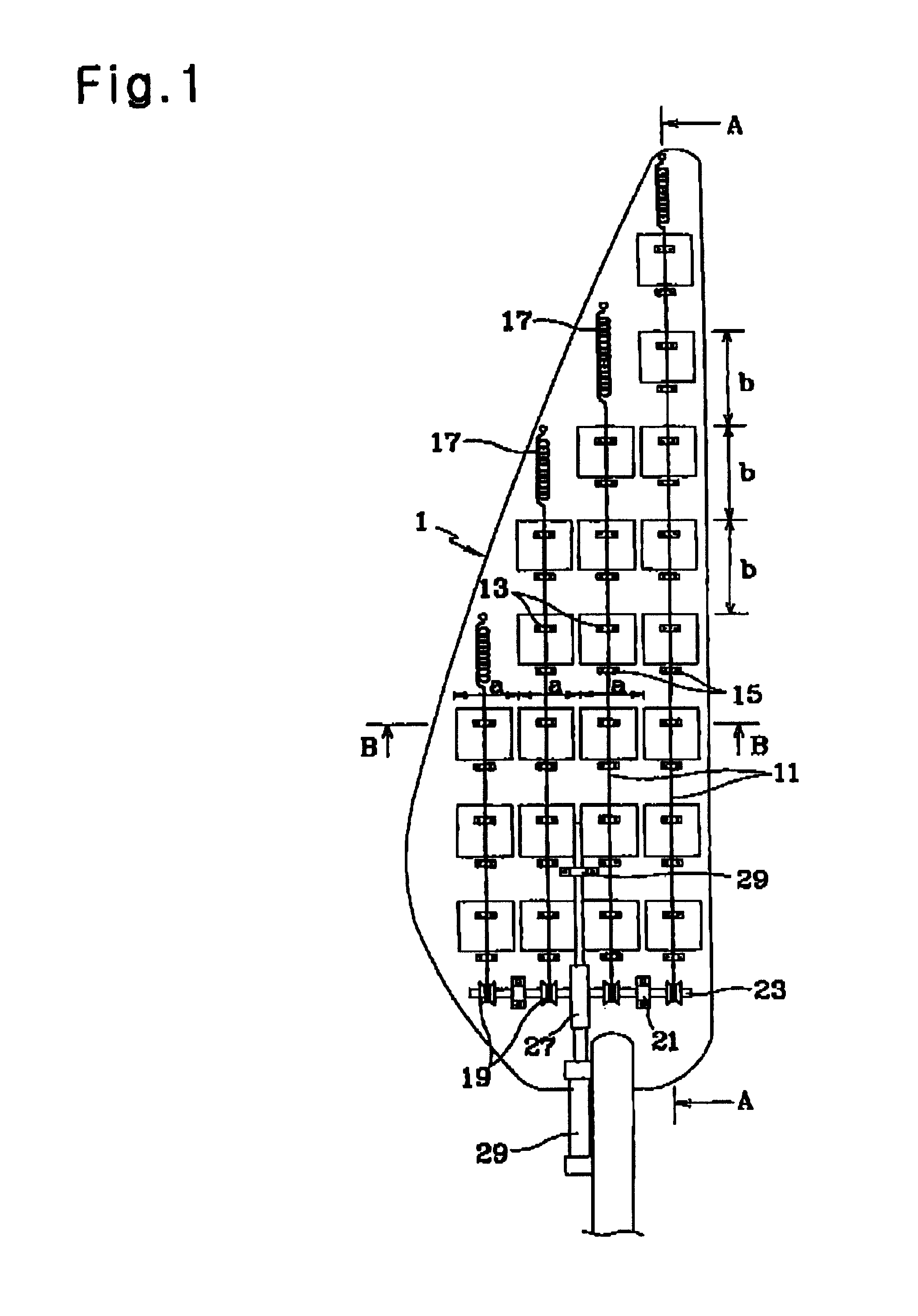
[0057]FIG. 1 is a front view illustrating an example of a windmill blade according to the present invention. The windmill blade includes blade bodies 1 each having a desired shape. Three blade bodies 1 are arranged along a rotation direction while being uniformly spaced apart from one another. The blade bodies 1 form a blade assembly, that is, the windmill blade, adapted to receive pressure of wind to rotate.

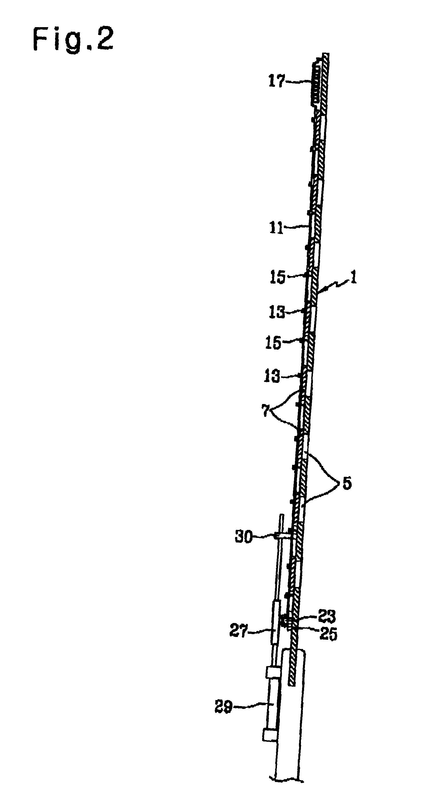
[0058]As shown in FIGS. 2, 3, and 4, each blade body 1 is provided with a plurality of wind pressure adjusting holes S arranged while being uniformly spaced apart from one another. Each wind pressure adjusting hole 5 is adapted to vary the wind pressure receiving area thereof depending on a variation in the force of wind.

[0059]The wind pressure adjusting holes 5 are arranged in several columns. Preferably, the space, a, between adjacent columns of the wind...


PUM


Abstract

Disclosed is a wind power generating apparatus in which windmill blades are mounted in a multi-stage fashion to a rotating shaft while being spaced apart from one another to efficiently generate wind power. Each windmill blade includes blade bodies mounted to the rotating shaft, and provided with wind pressure adjusting holes, wind pressure adjusting plates coupled to each blade body, and connected together to a wire, each wind pressure adjusting plate being slidable along guides respectively arranged at opposite sides of the associated wind pressure adjusting hole to adjust an opening degree of the wind pressure adjusting hole, elastic members each adapted to connect one end of the associated wire to the associated blade body, and winches each adapted to connect the other end of the associated blade body, the winches being mounted to a single shaft to simultaneously wind or unwind all wire.

Description

TECHNICAL FIELD[0001]The present invention relates to an apparatus for generating power using wind force, and more particularly to a windmill blade capable of varying the wind pressure receiving area thereof depending on a variation in the force of wind, thereby achieving an enhancement in the efficiency of utilizing the pressure of wind without being damaged by strong force of wind.BACKGROUND ART[0002]Generally, a windmill is a device for generating power using the force of an air flow which is spontaneously generated in the Earth's atmosphere, and then dissipated. Such a windmill includes at least one blade adapted to receive a lift force caused by the force of a wind so that it rotates.[0003]Such a windmill blade should have a construction capable of generating a lift force even when it receives a weak wind force, while rotating continuously and smoothly without being damaged by a strong wind force. In order to generate a lift force with a weak wind force, the windmill blade shou...

Claims


Application Information

Patent Timeline
Patent Type & Authority Patents(United States)
IPC IPC(8): F03D7/04F03D11/00F03D1/00F03D1/06F03D7/02F03D11/02F03D11/04
CPCF03D1/0633F03D7/0236Y02E10/723F05B2240/313Y02E10/721F05B2240/30Y02E10/72
Inventor JANG, KEUN-SUK
Owner JANG KEUN SUK
Why Eureka
Try Eureka