Magnetic resonance method and system forming an isotropic, high resolution, three-dimensional diagnostic image of a subject from two-dimensional image data scans

a magnetic resonance and image data technology, applied in the field of system and method for improving the resolution and tissue contrast in mri, can solve the problems of low contrast, small and intricate musculoskeletal structures to be imaged, and noisy mri images, so as to improve tissue contrast, improve inter-slice resolution and tissue contrast, the effect of improving the resolution and tissue contras

Inactive Publication Date: 2006-01-10
VIRTUALSCOPICS
View PDF24 Cites 93 Cited by
  • Summary
  • Abstract
  • Description
  • Claims
  • Application Information

AI Technical Summary

Benefits of technology

[0010]Therefore, it is an object of the present invention to increase inter-slice resolution.
[0011]It is another object of the present invention to improve tissue contrast.
[0012]It is still another object of the present invention to improve inter-slice resolution and tissue contrast simultaneously.
[0013]It is yet another object to provide a simple technique for image registration.

Problems solved by technology

However, MRI often introduces the following technical challenges.
Many of the anatomical structures to be visualized require high resolution and present low contrast, since, for example, many of the musculoskeletal structures to be imaged are small and intricate.
MRI images can also be noisy.
In particular, MRI has the following limitations in resolution and tissue contrast.
Although current MRI machines can achieve relatively high intra-plane resolution, the inter-slice resolution is not so good as the intra-plane resolution; also, the inter-slice resolution is limited by the ability of the system to stimulate a single spatial slice or section.
Although tissue contrast can be adjusted by selecting the right pulse sequence, analysis of a single pulse sequence is not enough to differentiate among adjacent similar tissues.
In other words, the resolution is typically poor in the out-of-plane dimension, and the contrast is typically low between soft tissue structures.

Method used


Image

  • Magnetic resonance method and system forming an isotropic, high resolution, three-dimensional diagnostic image of a subject from two-dimensional image data scans
  • Magnetic resonance method and system forming an isotropic, high resolution, three-dimensional diagnostic image of a subject from two-dimensional image data scans
  • Magnetic resonance method and system forming an isotropic, high resolution, three-dimensional diagnostic image of a subject from two-dimensional image data scans

Examples


Embodiment Construction

[0028]A preferred embodiment of the present invention will now be set forth in detail with reference to the drawings.

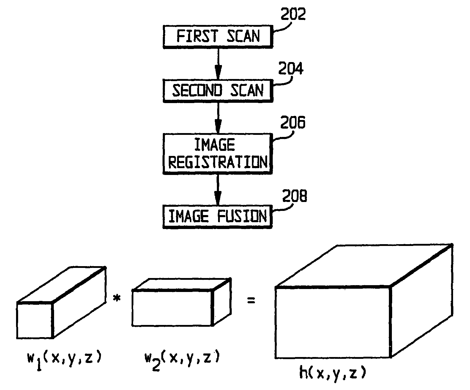
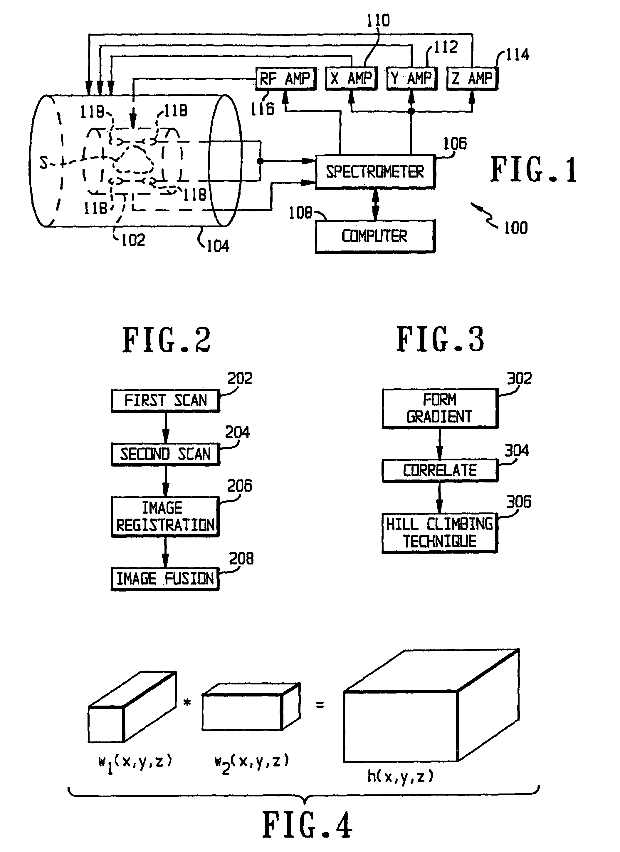
[0029]FIG. 1 shows a block diagram of an MRI system 100 on which the present invention can be implemented. The system 100 uses an RF coil 102 and a gradient coil 104 to apply the required RF and gradient fields to the subject S. A spectrometer 106, acting under the control of a computer 108, generates gradient signals which are amplified by an X amplifier 110, a Y amplifier 112 and a Z amplifier 1.14 and applied to the gradient coil 104 to produce the gradient fields. The spectrometer 106 also generates RF signals which are amplified by an RF amplifier 116 and applied to the RF coil 102 to produce the RF fields. The free induction decay radiation from the sample S is detected by the RF coil 102 or by one or more local receiving coils 118 and applied to the spectrometer 106, where it is converted into a signal which the computer 108 can analyze.

[0030]The computer 108 s...


PUM


Abstract

MRI scans typically have higher resolution within a slice than between slices. To improve the resolution, two MRI scans are taken in different, preferably orthogonal, directions. The scans are registered by maximizing a correlation between their gradients and then fused to form a high-resolution image. Multiple receiving coils can be used. When the images are multispectral, the number of spectral bands is reduced by transformation of the spectral bands in order of image contrast and using the transformed spectral bands with the highest contrast.

Description

[0001]This is a division of Appl. No. 09 / 540,524, filed Mar. 31, 2000.BACKGROUND OF THE INVENTION[0002]1. Field of the Invention[0003]The present invention is directed to a system and method for improving the resolution and tissue contrast in MRI.[0004]2. Description of Related Art[0005]The best current source of raw image data for observation of a complex soft tissue and bone structure is magnetic resonance imaging (MRI). MRI involves the transmission of RF signals of predetermined frequency (e.g., approximately 15 MHZ in some machines, the frequency depending upon the magnitude of magnetic fields employed and the magnetogyric ratio of the atoms to be imaged). Typically, exciting pulses of RF energy of a specific frequency are transmitted via an RF coil structure into an object to be imaged. A short time later, radio-frequency NMR responses are received via the same or a similar RF coil structure. Imaging information is derived from such RF responses.[0006]In MRI, a common imaging ...

Claims


Application Information

Patent Timeline
Patent Type & Authority Patents(United States)
IPC IPC(8): G01V3/00A61B5/055G06K9/00G01R33/20G01R33/32G01R33/54G01R33/56
CPCA61B5/055G01R33/4835G01R33/5608A61B5/4528
Inventor TAMEZ-PENA, JOSETOTTERMAN, SAARA MARJATTA SOFIAPARKER, KEVIN J.
Owner VIRTUALSCOPICS
Why Eureka
Try Eureka