
HF wheel rim antenna having several patch antennas

Inactive Publication Date: 2006-01-10
ROBERT BOSCH GMBH
View PDF6 Cites 10 Cited by
  • Summary
  • Abstract
  • Description
  • Claims
  • Application Information

AI Technical Summary

Benefits of technology

[0005]The data transmission between a primary side communications antenna and the secondary antennas can take place either continuously or at predefined times, e.g., upon request of a stationarily positioned processing unit. For non-continuous data transmission, considerable power savings can be achieved.
[0015]According to another exemplary embodiment of the present invention, on the secondary antenna side, for example, a device is provided which selects a group of one or more secondary antennas for data exchange, which group is situated favorably for communications with the communications antenna. This has the advantage that not all secondary antennas need to participate in the communications, and therefore energy is saved.

Problems solved by technology

Data transmission from a fast moving or rotating system, such as a vehicle tire, on the other hand, is limited to certain positions of the rotating body and / or the secondary antenna system positioned on it, or is a function of the speed of the moving body.

Method used


Image

  • HF wheel rim antenna having several patch antennas
  • HF wheel rim antenna having several patch antennas
  • HF wheel rim antenna having several patch antennas

Examples


Embodiment Construction

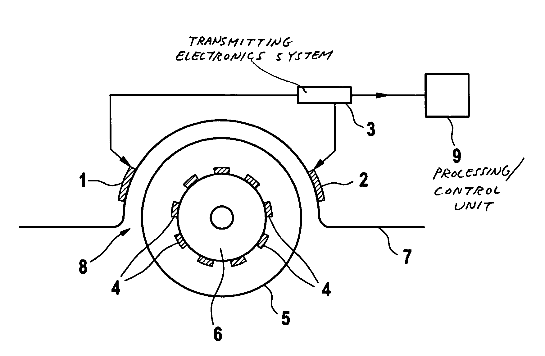
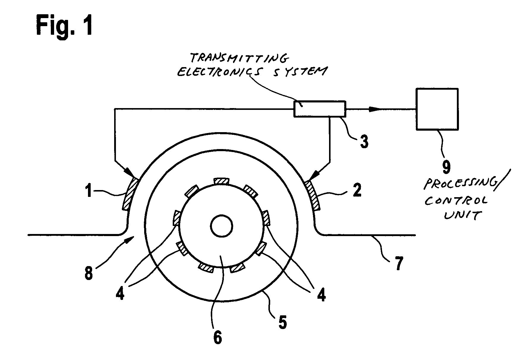
[0020]FIG. 1 shows a wheel rim antenna system for transmitting data, e.g., the tire pressure or the tire temperature, from the interior of a vehicle tire 5. The antenna system includes two primary antennas 1, 2 that are situated in wheel housing 8 of a vehicle 7, and several secondary antennas 4 situated on a wheel rim 6. In this context, the secondary antennas 4 are positioned in circular fashion at the outer circumference of wheel rim 6.

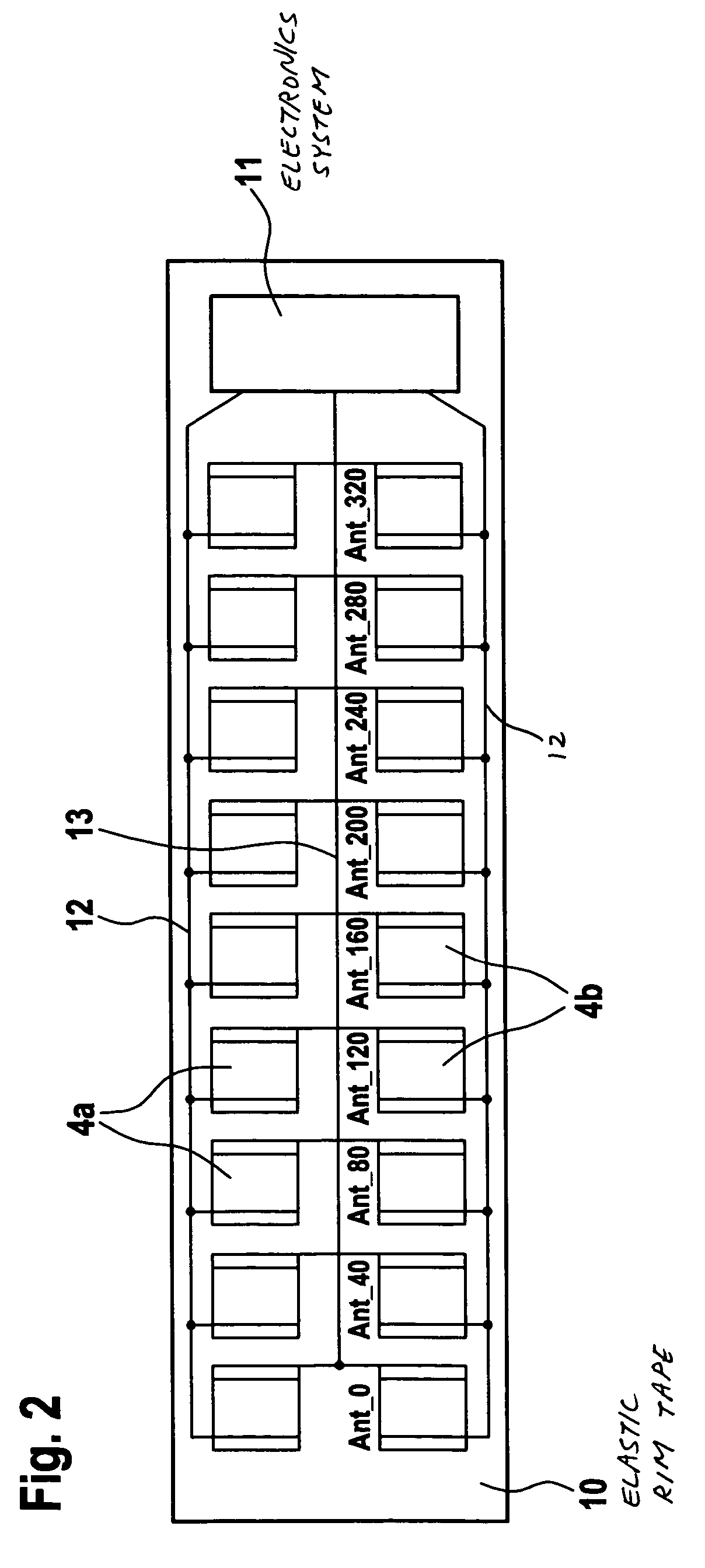
[0021]Primary antennas 1, 2 may be normally operated in such a way that both primary antennas 1, 2 operate as transmitting antennas to supply a sub-system including the secondary antennas 4 and an associated electronics system 11 (shown in FIG. 2) on the secondary antenna side with energy. Primary antenna 2 may be switched over to communications operation if an instruction to read out data from wheel 5 is provided from a processing / control unit 9. Therefore, primary antenna 2 may also be designated as a communications antenna 2, and primary antenna...


PUM


Abstract

A system for wireless data transmission between a stationary transmitting / reception device and a rotating body, e.g., a vehicle wheel, having secondary antennas, is provided. A plurality of stationary primary antennas are coupled to the stationary transmitting / reception device, and a plurality of secondary antennas are positioned along a circumference of the rotating body. Amongst the plurality of primary antennas, at least one primary antenna is provided for transmitting electrical energy to the secondary antennas, and at least one other primary antenna is provided for communications with the secondary antennas. In this manner, data transmission independent of the speed of the rotating body and the position of the secondary antennas is achieved.

Description

FIELD OF THE INVENTION[0001]The present invention relates to a device for wireless data transmission between a stationary transmission / reception device (primary antenna) and an antenna set-up (secondary antenna) situated on a rotating body, e.g., in a vehicle tire.BACKGROUND INFORMATION[0002]Systems for wireless data transmission that utilize the energy contained in the field of the transmitting antenna for data transmission are also known as TAG systems. These systems include a primary antenna for sending a carrier signal to a secondary antenna using an electronic system which, while utilizing the energy contained in the radio hop, transmits back a useful signal (measuring signal) to the primary antenna. The useful signal is evaluated in the reception section of the primary antenna by an evaluation unit. In a system at rest, i.e., the primary and secondary antenna are situated in a stationary manner, this data transmission causes relatively few problems. Data transmission from a fa...

Claims


Application Information

Patent Timeline
IPC IPC(8): H01Q1/32B60C23/04H04B7/06H04B7/08
CPCB60C23/0408B60C23/0444H04B7/0608H04B7/0805H04B7/0834H04B7/0825H04B7/0613
Inventor VOIGTLAENDER, KLAUSTHIEL, MICHAELTENTEN, WILFRIEDDAMM, KLAUS
Owner ROBERT BOSCH GMBH
Learn More