Method and circuit for controlling the refresh rate of sampled reference voltages

a reference voltage and refresh rate technology, applied in the direction of electric variable regulation, process and machine control, instruments, etc., can solve the problems of counteracting the desired power saving, reducing the voltage of the sampling capacitor, and large power consumption and chip area needed to implement circuitry, etc., to achieve the effect of reducing power consumption

Active Publication Date: 2011-07-19
TEXAS INSTR INC
View PDF9 Cites 4 Cited by
  • Summary
  • Abstract
  • Description
  • Claims
  • Application Information

AI Technical Summary

Benefits of technology

[0009]A big advantage of the present invention is automatic adjustment to temperature changes. The whole circuitry experiences basically the same temperature behavior as the sampling capacitor and its environment. Thus the first and second leakage currents increase and decrease according to the temperature of the integrated device. There is no need to resort to a fixed refresh cycle for the worst case leakage current which occurs at high temperatures. This invention flexibly adapts the refresh time and thereby achieves considerable power savings.
[0010]The factor N can be between 5 and 20. The initial voltage on the first capacitor at the beginning of a sampling period can be 1.6 V and the initial voltage level on the second capacitor at the beginning of the sampling period can be 1.2 V. The leakage current source can be a reverse biased diode element. These are only examples. There are many other ways to implement and dimension structures according to the present invention.
[0011]The present invention provides a method for controlling the refresh rate of a reference voltage sampled on a sampling capacitor. This method includes sampling a first voltage on a first capacitor, sampling a second voltage smaller than the first voltage on a second capacitor, discharging the first capacitor by a first leakage current and discharging the second capacitor by a second leakage current. The method compares the voltages on the first capacitor and the second capacitor during discharge of the capacitors. The method triggers a refresh of the reference voltage on the sampling capacitor when the voltage levels on the capacitors are equal.

Problems solved by technology

The voltage on the sampling capacitor decreases over time primarily by parasitic leakage currents.
Accordingly, the power consumption and the chip area needed to implement the circuitry is large.
This counteracts the desired power savings.
Accordingly, both the refresh rate and the power consumption are unnecessarily high.

Method used


Image

  • Method and circuit for controlling the refresh rate of sampled reference voltages
  • Method and circuit for controlling the refresh rate of sampled reference voltages
  • Method and circuit for controlling the refresh rate of sampled reference voltages

Examples


Embodiment Construction

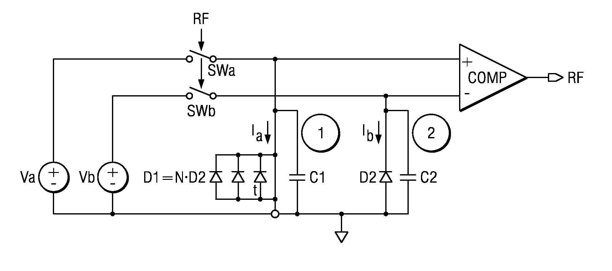
[0018]FIG. 1 illustrates a simplified circuit diagram overview of a system using sampled reference voltages. A reference voltage source Vref produces a reference voltage. This reference voltage is sampled on multiple sampling capacitors Csamp by corresponding switches SW. When the reference voltage is sampled on the sampling capacitors Csamp the switches SW open and the reference voltage generator Vref is switched off by an enable signal applied to the input POFF. The reference voltages on the sampling capacitors are used for several different stages P1, P2 and P3. These may include electronic circuitry such as a low-drop-out (LDO) supply voltage generator or different circuitry. Power savings are achieved by switching off the reference voltage generator Vref. Timing for the refresh of the capacitors must be determined by a control loop such as the one shown in FIG. 2.

[0019]FIG. 2 illustrates a simplified circuit diagram of a control loop for the reference voltage on the sampling ca...


PUM

PropertyMeasurementUnit
voltageaaaaaaaaaa
voltageaaaaaaaaaa
voltageaaaaaaaaaa

Abstract

The present invention relates to controlling the refresh rate of the reference voltage on a sampling capacitor (Csamp). A comparator (COMP) compares the voltage on a first capacitor (C1) with the voltage on a second capacitor (C2). These capacitors have the capacitance of the sampling capacitor (Csamp). Upon each refresh the first capacitor (C1) samples a first voltage (Va) and the second capacitor samples a lower second voltage (Vb). The first capacitor (C1) is discharged at a first current Ia via a first leakage current source (D1). The second capacitor (C2) is discharged at a second current Ib via a second leakage current source (D2). The comparator (COMP) triggers a refresh when the voltages equal. The first current Ia is preferably an integer N times the second current Ib.

Description

CLAIM OF PRIORITY[0001]This application claims priority under 35 U.S.C. 119(a) to German Patent Application No. 10 2007 031 055.4 filed Jul. 4, 2007 and 35 U.S.C. 119(e)(1) to U.S. Provisional Application No. 61 / 016,725 filed Dec. 26, 2007.TECHNICAL FIELD OF THE INVENTION[0002]The technical field of this invention is controlling the refresh rate of a reference voltage sampled on a sampling capacitor and an electronic device with a corresponding circuit.BACKGROUND OF THE INVENTION[0003]An approach to saving power in integrated electronic devices involves sampling a reference voltage. This reference voltage is usually generated by a band gap reference generator on a capacitor. While the reference voltage is stored on the sampling capacitor, the reference generator circuit can be switched off or put in a power down mode to reduce static power consumption. This reduces the average supply current of the reference generator and leads to lower power consumption.[0004]The voltage on the sam...

Claims


Application Information

Patent Timeline
Patent Type & Authority Patents(United States)
IPC IPC(8): H01M10/46
CPCG05F3/30G11C5/147G11C27/026
Inventor GERBER, JOHANNESARNOLD, MATTHIASHUBER, KORBINIAN
Owner TEXAS INSTR INC
Why Eureka
Try Eureka