
Imaging lens

a technology of imaging lens and peripheral components, applied in the field of imaging lenses, can solve the problems of insufficient suited for a wide picture angle, difficult to suppress distortion aberration with high resolution, and small peripheral components for mounting imaging lenses on the image pickup device side, etc., to achieve wide picture angle, compact, and favorable optical performance.

Inactive Publication Date: 2006-01-10
FUJI PHOTO OPTICAL CO LTD
View PDF7 Cites 25 Cited by
  • Summary
  • Abstract
  • Description
  • Claims
  • Application Information

AI Technical Summary

Benefits of technology

[0006]The present invention relates to an imaging lens having favorable optical performance, a wide picture angle, and is relatively compact. The present invention further relates to an imaging lens designed for use with an image pickup device in a text imaging camera or a similar apparatus.

Problems solved by technology

The suppression of distortion aberration with high resolution is especially difficult, but necessary, with a wide picture angle provided by a wide-angle imaging lens in a text imaging camera or similar device.
However, in recent years, peripheral components for mounting an imaging lens on the image pickup device side have been getting smaller, and this necessitates making the accompanying imaging lens system smaller as well.
However, the lenses described in these Japanese applications are designed for use primarily in digital cameras and not adequately suited for a wide picture angle as needed in a text imaging camera.
Furthermore, because the imaging lens of Japanese Laid-Open Patent Application 2001-100092 uses an aspheric surface in a cemented lens component, the imaging lens is expensive to manufacture, making it impractical for mass production.

Method used


Image

  • Imaging lens
  • Imaging lens
  • Imaging lens

Examples


embodiment 1

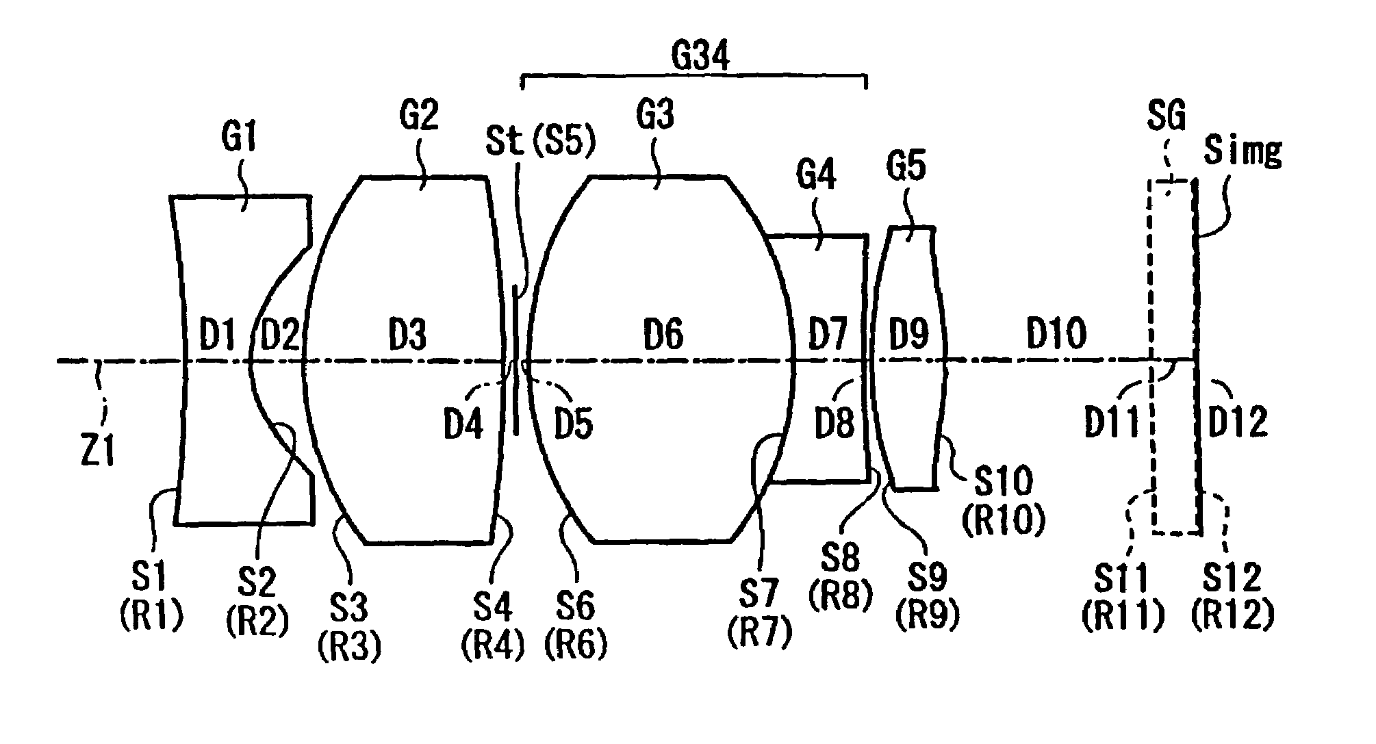
[0040]FIG. 1 shows Embodiment 1 of the present invention. Table 1 below lists the surface number #, in order from the object side, the radius of curvature R (in mm) of each surface near the optical axis, the on-axis surface spacing D (in mm), as well as the refractive index Nd and the Abbe number νd (both at the d-line of 587.6 nm) of each optical element for Embodiment 1.

[0041]

TABLE 1#RDNdνd 1*−9.320.301.5156.0 2*0.460.24 31.410.901.6236.3 4−5.350.06 5∞ (stop)0.06 61.321.211.7552.3 7−1.320.321.8523.8 87.610.04 9*2.450.331.5156.0 10*−1.280.9511∞0.201.5264.112∞0.02

[0042]The surfaces with a * to the right of the surface number in Table 1 are aspheric lens surfaces, and the aspheric surface shape is expressed by Equation (A) above.

[0043]Table 2 below lists the values of the constants K, A4, A6, A8, and A10 used in Equation (A) for each of the aspheric lens surfaces of Table 1. Aspheric coefficients that are not present in Table 2 are zero. An “E” in the data indicates that the number f...

embodiment 2

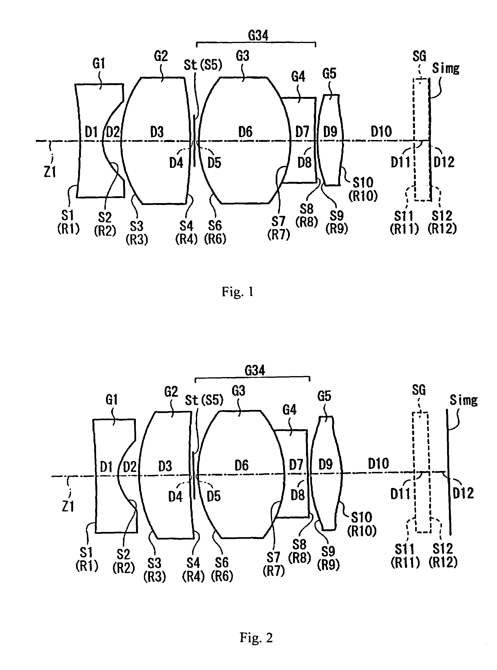
[0048]FIG. 2 shows Embodiment 2 of the present invention. Embodiment 2 differs from Embodiment 1 in that the image-side surface S4 of the second lens element G2 is concave rather the convex as in Embodiment 1. Table 3 below lists the surface number #, in order from the object side, the radius of curvature R (in mm) of each surface near the optical axis, the on-axis surface spacing D (in mm), as well as the refractive index Nd and the Abbe number νd (both at the d-line of 587.6 nm) of each optical element for Embodiment 2.

[0049]

TABLE 3#RDNdνd 1*−11.180.301.5156.0 2*0.470.27 31.660.661.7328.6 48.960.06 5∞ (stop)0.06 61.311.141.7454.5 7−1.310.301.8522.8 848.380.04 9*2.290.401.5156.0 10*−1.120.9511∞0.201.5264.112∞0.26

[0050]The surfaces with a * to the right of the surface number in Table 3 are aspheric lens surfaces, and the aspheric surface shape is expressed by Equation (A) above.

[0051]Table 4 below lists the values of the constants K, A4, A6, A8, and A10 used in Equation (A) for each...

embodiment 3

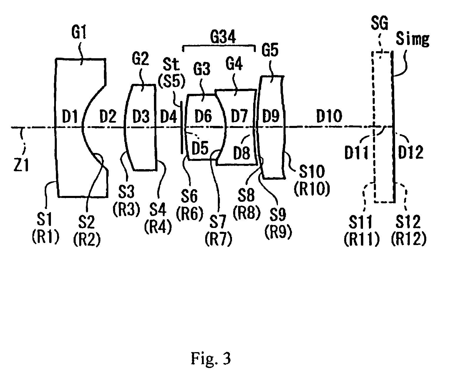
[0056]FIG. 3 shows Embodiment 3 of the present invention. Embodiment 3 differs from Embodiment 1 in that the object-side surface S1 of the first lens element G1 is convex rather than concave as in Embodiment 1 (as well as in Embodiment 2), in that the image-side surface S4 of the second lens element G2 is concave (as in Embodiment 2) rather than convex as in Embodiment 1, and in that the object-side lens surface S9 of lens element G5 is spherical rather than aspheric as in Embodiment 1 (as well as in Embodiment 2). Table 5 below lists the surface number #, in order from the object side, the radius of curvature R (in mm) of each surface near the optical axis, the on-axis surface spacing D (in mm), as well as the refractive index Nd and the Abbe number νd (both at the d-line of 587.6 nm) of each optical element for Embodiment 3.

[0057]

TABLE 5#RDNdνd 1*7.500.301.5355.5 2*0.460.45 31.180.331.8236.1 415.170.28 5∞ (stop)0.04 61.570.431.8246.2 7−0.660.301.7527.3 82.380.04 92.670.301.5355.5 ...


PUM


Abstract

An imaging lens includes, in order from the object side: a first lens component of negative refractive power with two aspheric surfaces including a concave surface near the optical axis on the image-side; a second lens component of positive refractive power with a convex surface on the object side; a third lens component having positive refractive power and including lens elements having positive and negative refractive powers; and a fourth lens component having an aspheric surface on the image side that is convex near the optical axis and is concave at the periphery. The imaging lens satisfies a specified condition to assure a sufficient back focus for insertion of additional optical elements, a sufficiently small imaging lens diameter, and favorable correction of aberrations. The imaging lens has a wide picture angle, consists of only 5 lens elements in the disclosed embodiments, and is particularly suited for a text imaging camera.

Description

BACKGROUND OF THE INVENTION[0001]Systems used to electronically capture a picture image using an image pickup device, such as a text imaging camera, are well known. For example, a presentation system is well known that uses a text imaging camera to form an image of a written document, or similar document, as an electronic image and then displays a greatly enlarged version of this image using a device that provides a greatly enlarged image, such as a projector. Additionally, this image may be sent through a teleconferencing system that includes a communications network in order to display versions of this image at various remote locations.[0002]With image pickup devices such as a text imaging camera, an image pickup device such is a CCD (Charged Coupled Device) or a CMOS (Complementary Metal Oxide Semiconductor) is used. Imaging lenses for use with such image pickup devices have been developed for use in digital cameras. For example, Japanese Laid-Open Patent Application 2001-021800 ...

Claims


Application Information

Patent Timeline
IPC IPC(8): G02B9/34G02B13/18G02B13/06G02B13/04
CPCG02B13/06
Inventor SHINOHARA, YOSHIKAZU
Owner FUJI PHOTO OPTICAL CO LTD
Learn More