
Capacitors including track-etched separator materials

Inactive Publication Date: 2006-01-10
MEDTRONIC INC
View PDF31 Cites 19 Cited by
  • Summary
  • Abstract
  • Description
  • Claims
  • Application Information

AI Technical Summary

Benefits of technology

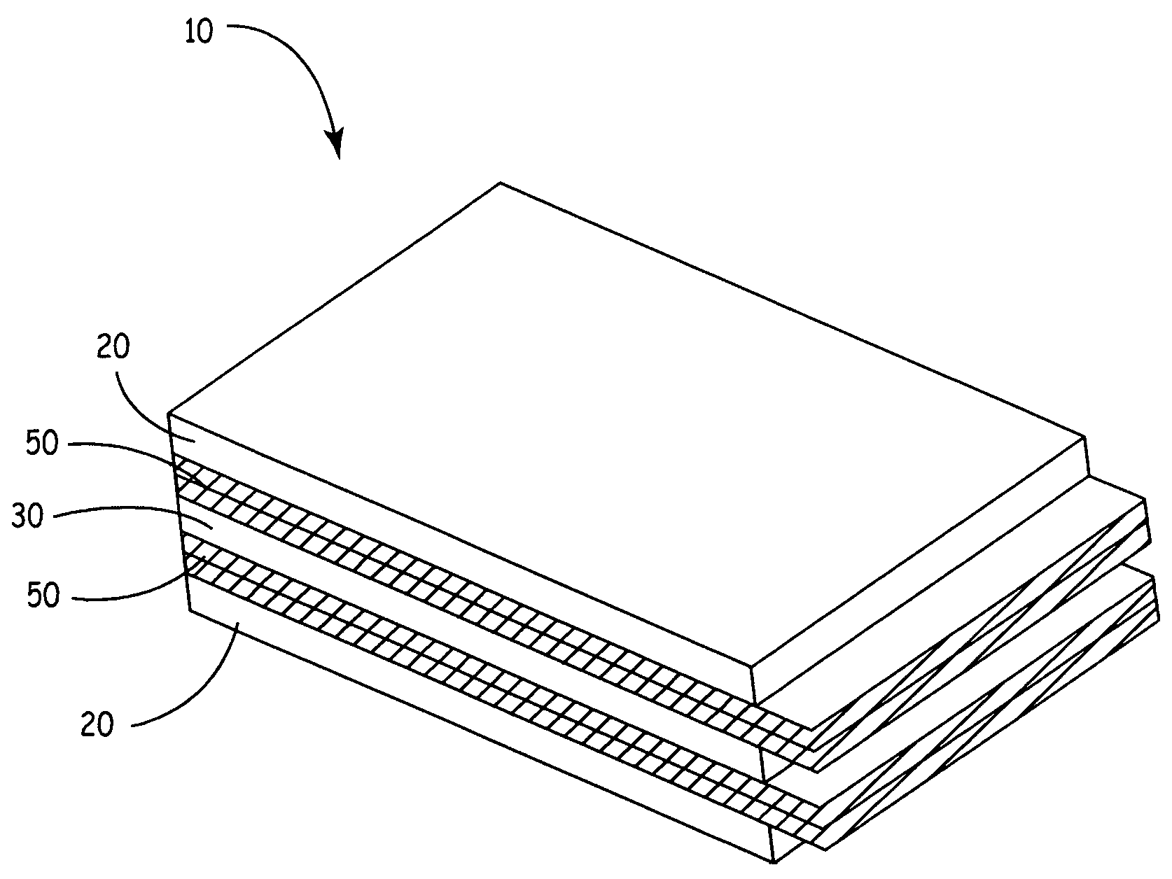
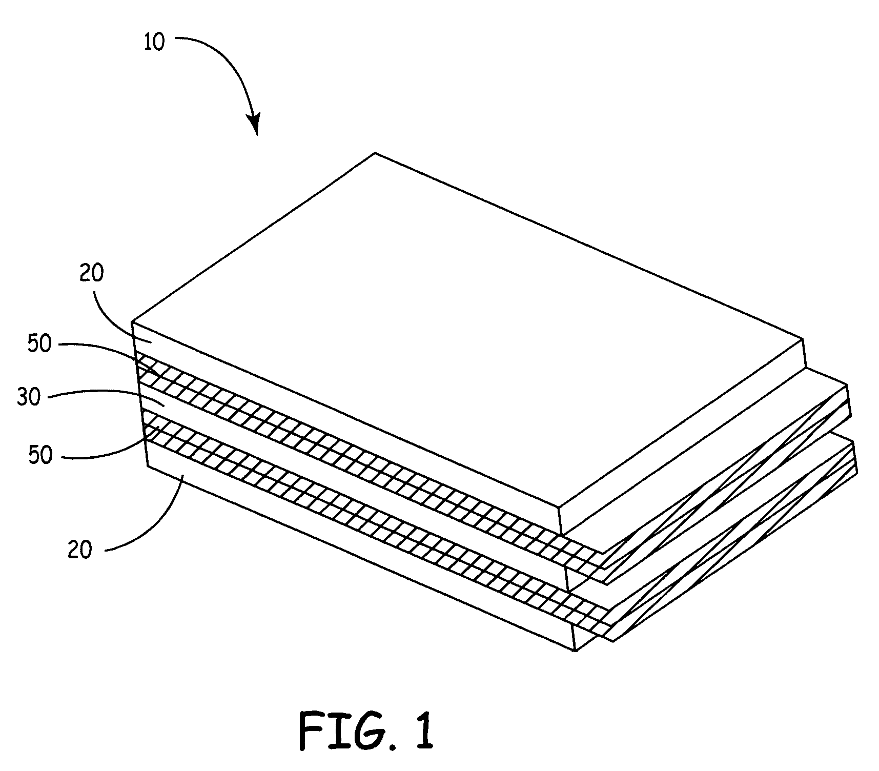
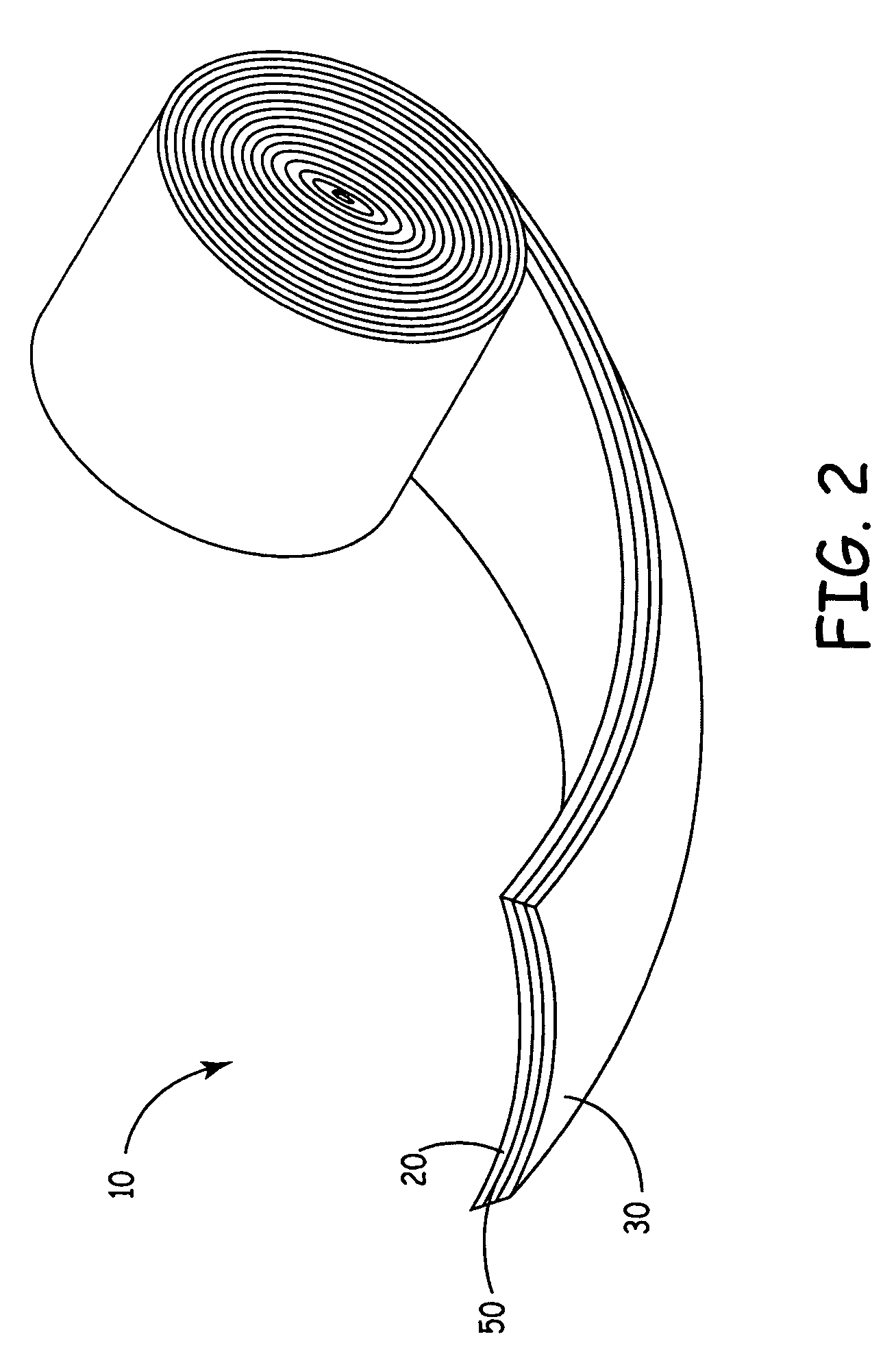
[0021]In preferred embodiments, the present invention includes a capacitor cell comprising anode material, cathode material, an electrolyte operatively associated with the anode material and the cathode material, and a separator material comprising track-etched materials. The track-etched separator material is provided in between the anode material and the cathode material to prevent internal electrical short circuit conditions and to allow sufficient movement of the electrolyte within the cell.

Problems solved by technology

One drawback with current batteries and capacitors is that they are often large in size, which in turn causes the total size of the defibrillator to be relatively large in size.
A patient who has such a device implanted may be bothered by the presence of such a large object in the chest area.
One drawback is that current separator materials are often very thick.
The use of thick separator materials makes it difficult to manufacture capacitors having decreased sizes.
A further difficulty with prior separators is that they do not have strong enough tensile properties.
Single sheets of paper separator materials alone do not have strong tensile properties.
However, thick paper separators are undesirable, as more space is needed to contain the capacitor.
Another drawback with prior separators is that separator materials often unpredictably swell or expand when impregnated with liquid electrolyte.
This swelling often causes the remaining capacitor elements to be pushed outward, which often results in swelling of the capacitor enclosure.
The swelling may also cause damage to capacitor elements, rendering the capacitor dysfunctional.
In order to account for this swelling, a larger-sized capacitor enclosure is sometimes used, again causing an undesirable increase in the amount of space needed to contain the capacitor.
A yet another drawback with prior separators is that porosity is not precisely controlled.
While porous polymers are currently used as separator materials, it has often been difficult to precisely control their porosity so that separator performance can be optimized.

Method used


Image

  • Capacitors including track-etched separator materials
  • Capacitors including track-etched separator materials
  • Capacitors including track-etched separator materials

Examples


Embodiment Construction

[0026]The present invention comprises a separator for use in a capacitor cell that comprises track-etched material. In various embodiments of the present invention, the separator comprises a track-etched polymer. In preferred embodiments, the separator comprises a track-etched polycarbonate. Typically, track-etched membranes are formed by bombarding a film of material with energy particles that form tracks of damaged material through the film. The film is then subjected to a chemical agent that selectively etches the damaged tracks to create pores through the film.

[0027]The track-etching process is well known in the art and many variations of the process exist. Examples of processes for forming track-etched membranes are disclosed in U.S. Pat. Nos. 3,303,805; 3,493,751; 3,612,871; 6,120,875; 3,662,178; 3,673,017; 3,677,844; 3,713,921; 3,802,972; 3,852,134; 4,855,049; 4,956,219; 5,139,624; 5,449,917; 5,914,150, the entire contents of each of which are incorporated herein by reference...


PUM

PropertyMeasurementUnit
Surface areaaaaaaaaaaa

Abstract

The present invention relates generally to capacitor cells and the utilization of enhanced separator materials in such cells. More specifically, the present invention is related to the utilization of track-etched materials as the separator materials in capacitor cells. Methods of making a capacitor cell having a track-etched separator material is also disclosed.

Description

CROSS REFERENCE TO RELATED APPLICATION[0001]This patent disclosure claims the benefit of prior provisional U.S. patent application Ser. No. 60 / 474,800, invented by Norton et al., filed 30 May 2003, and entitled, “Capacitor Cells Including Enhanced Separator Systems and Materials”—the contents of which are fully incorporated herein.FIELD OF THE INVENTION[0002]The present invention relates generally to capacitor cells and the utilization of enhanced separator materials in such cells. More specifically, the present invention is related to the utilization of track-etched separator materials for capacitor cells.BACKGROUND OF THE INVENTION[0003]Capacitor cells, such as batteries and capacitors, are particularly useful in various implantable medical devices, such as implantable defibrillators. Implantable defibrillators are implanted into the chests of patients prone to suffering ventricular fibrillation, a potentially fatal heart condition. Batteries and capacitors are critical components...

Claims


Application Information

Patent Timeline
IPC IPC(8): H01G9/00H01G9/02H01G9/145H01G9/15
CPCH01G9/02H01G9/151H01G9/145Y10T29/417
Inventor NORTON, JOHN D.
Owner MEDTRONIC INC
Learn More