Methods and apparatuses for implantable medical device telemetry power management

a technology of medical devices and power management, applied in the field of implantable medical devices, can solve the problems of inherently constrained device size and power consumption, poor synchronization of heart contraction patterns, and diminished blood circulation, and achieve the effects of increasing reliability, saving energy, and prolonging device li

Inactive Publication Date: 2006-01-10
CARDIAC PACEMAKERS INC
View PDF75 Cites 345 Cited by
  • Summary
  • Abstract
  • Description
  • Claims
  • Application Information

AI Technical Summary

Benefits of technology

[0021]Depending on a patient's needs for care and type of implantable device, one or more of the power-on methods and one or more of the power-off methods discussed in this document may be included in one implantable device. Using more than one method to connect / disconnect power from the energy source to the RF telemetry circuit increases the reliability of initiating and terminating the RF telemetry session in a timely manner to ensure patient safety and conserve energy and hence device longevity. Other aspects of the present systems, devices, and methods will become apparent upon reading the following Detailed Description and viewing the drawings that form a part thereof.

Problems solved by technology

Because such a device may be implanted in a patient for a long time, the size and power consumption of the device are inherently constrained.
Such rhythms result in diminished blood circulation.
CHF patients have deteriorated heart muscles that display less contractility and cause poorly synchronized heart contraction patterns.
One problem with inductive telemetry is its requirement that the two coils are closely placed.
Because the wand is electrically connected to the programmer using a cable, the inductive telemetry limits the patient's mobility.
However, RF telemetry may consume several thousand times more energy than inductive telemetry.

Method used


Image

  • Methods and apparatuses for implantable medical device telemetry power management
  • Methods and apparatuses for implantable medical device telemetry power management
  • Methods and apparatuses for implantable medical device telemetry power management

Examples


Embodiment Construction

[0052]In the following detailed description, reference is made to the accompanying drawings that form a part hereof, and in which is shown, by way of illustration, specific embodiments in which the invention may be practiced. These embodiments are described in sufficient detail to enable those skilled in the art to practice the invention, and it is to be understood that the embodiments may be combined, or that other embodiments may be utilized and that structural, logical and electrical changes may be made without departing from the scope of the present invention. The following detailed description is, therefore, not to be taken in a limiting sense, and the scope of the present invention is defined by the appended claims and their equivalents.

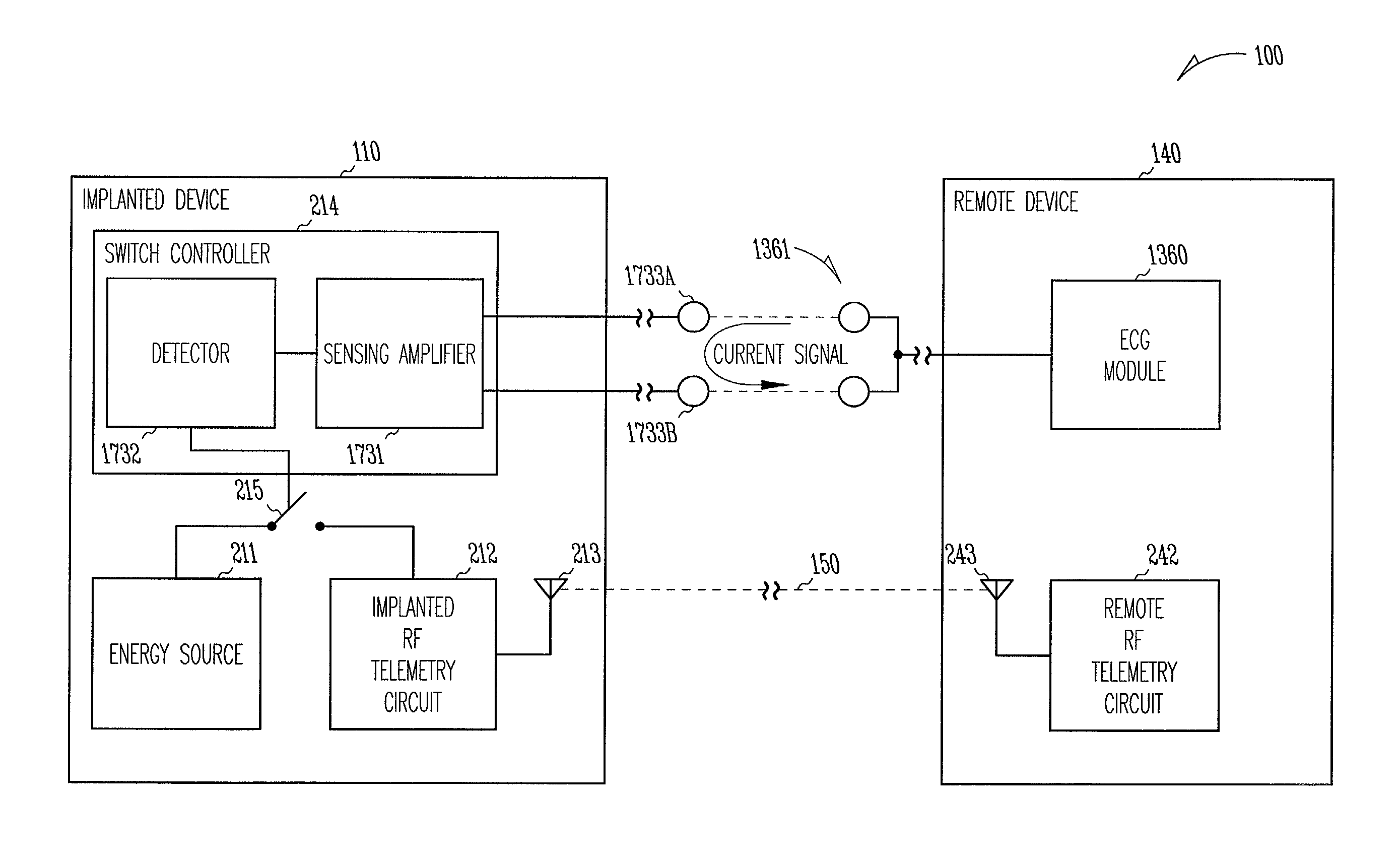
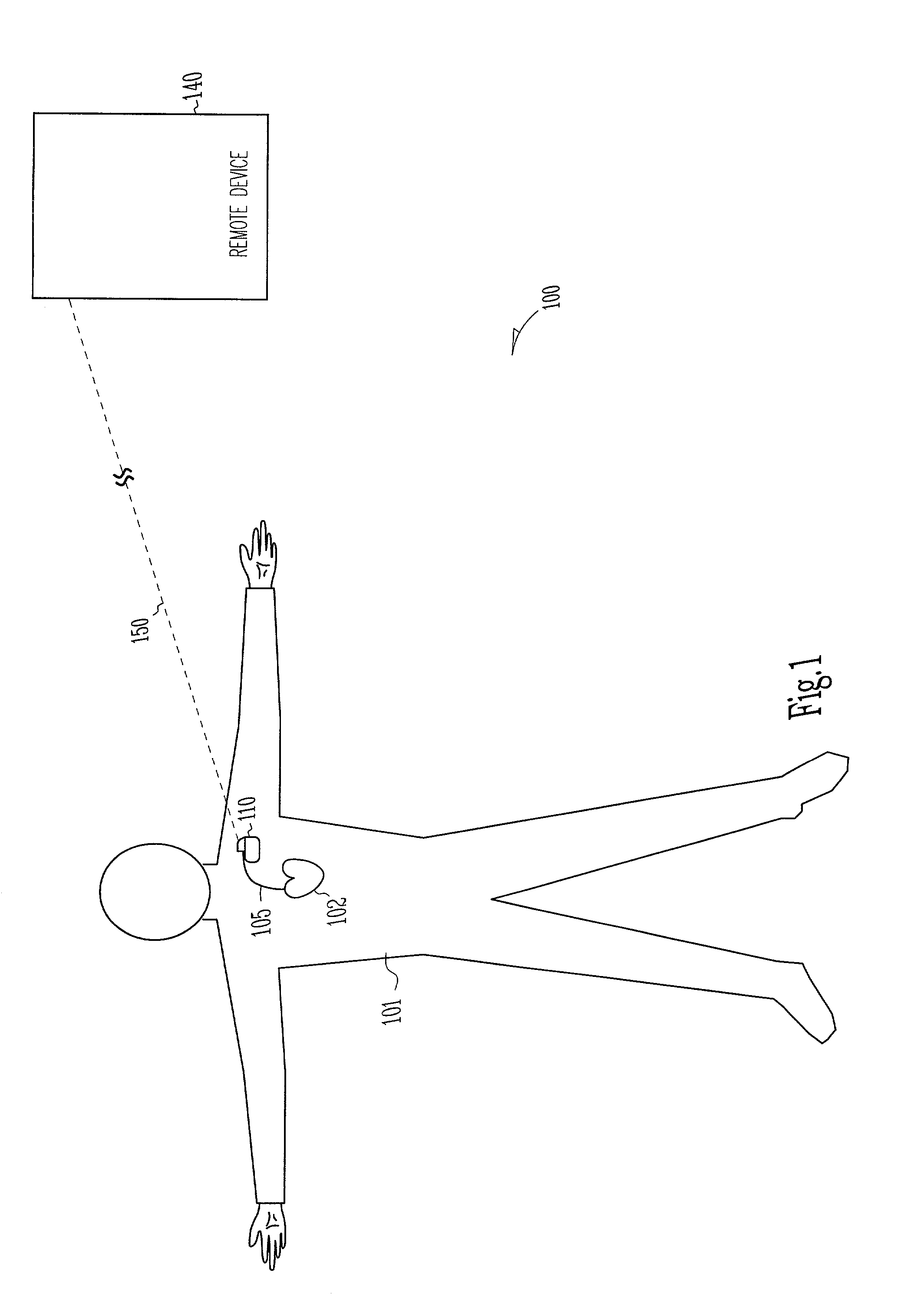
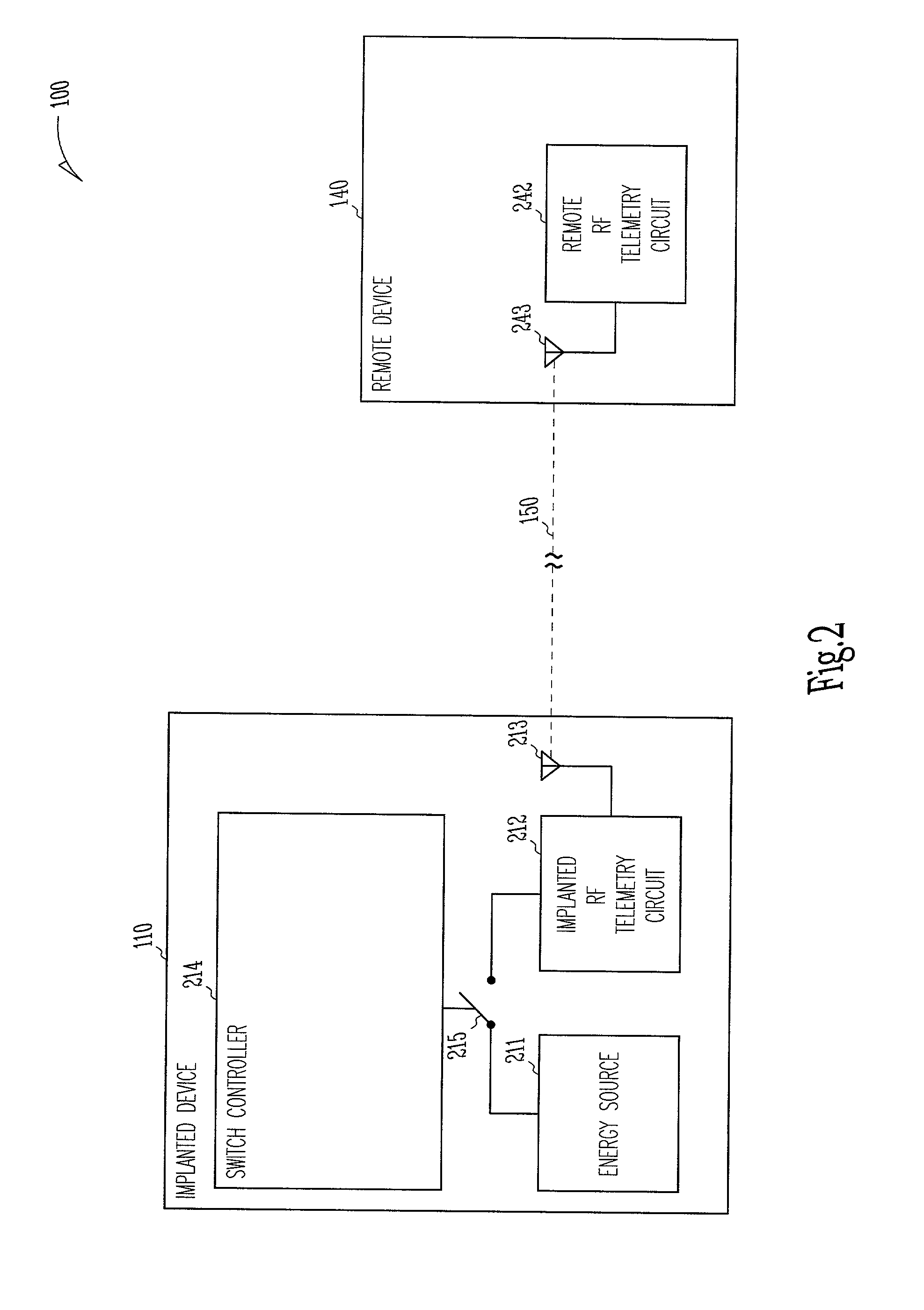
[0053]This document discusses, among other things, power management of telemetry circuit in an implantable medical device. The present methods and apparatuses will be described in applications involving implantable cardiac rhythm management sys...


PUM


Abstract

An implantable medical device includes a radio-frequency (RF) telemetry circuit and a power connection module through which the RF telemetry circuit is connected to an energy source such as a battery. The power connection module connects power from the energy source to at least one portion of the RF telemetry circuit when a user initiates an RF telemetry session. After the RF telemetry session is completed, the power connection module shuts off the at least one portion of the RF telemetry circuit. Power-on examples include a wireless telemetry activation signal received by a low power radio receiver in the implantable device, a physical motion detected by an activity sensor in the implantable device, an activation of an inductive telemetry circuit in the implantable device, a magnetic field detected by a magnetic field detector in the implantable device, and / or a telemetry activation signal detected by a sensing circuit included in the implantable device. Power-off examples include a wireless termination signal received by the implantable device, a delay timeout following the RF telemetry session, and / or a signal received by an inductive telemetry circuit in the implantable device.

Description

CROSS-REFERENCE TO RELATED APPLICATIONS[0001]This application is related to co-pending, commonly assigned Von Arx et al. U.S. patent application Ser. No. 10 / 025,223, entitled “A TELEMETRY DUTY CYCLE MANAGEMENT SYSTEM FOR AN IMPLANTABLE MEDICAL DEVICE,” filed Dec. 19, 2001 and Von An et al. U.S. patent application Ser. No. 10 / 025,183 entitled “AN IMPLANTABLE MEDICAL DEVICE WITH TWO OR MORE TELEMETRY SYSTEMS,” filed Dec. 19, 2001, each of which is hereby incorporated by reference.TECHNICAL FIELD[0002]This document relates generally to implantable medical devices and particularly, but not by way of limitation, to such a device including power management of a telemetry system allowing communication with an external device.BACKGROUND[0003]Medical devices are implanted in human bodies for monitoring physiological conditions, diagnosing diseases, treating diseases, or restoring functions of organs or tissues. Examples of such implantable medical devices include cardiac rhythm management sy...

Claims


Application Information

Patent Timeline
Patent Type & Authority Patents(United States)
IPC IPC(8): A61N1/362A61N1/08A61N1/372G06F19/00
CPCA61N1/08A61N1/37223A61N1/37276A61N1/3962A61N1/37A61N1/3925G06F19/3418A61N1/39622G16H40/40G16H40/67
Inventor VON ARX, JEFFREY A.YONCE, DAVID J.MAZAR, SCOTT T.LENT, KAREN M.HARRIS, THOMAS J.
Owner CARDIAC PACEMAKERS INC
Why Eureka
Try Eureka