
Workflow in a paperless office

a workflow and office technology, applied in the field of workflow systems, can solve the problems of not being able to say that paperless form-processing systems are in widespread use today, affecting the efficiency of workflow, and becoming difficult to give an accurate definition

Inactive Publication Date: 2006-01-10
IBM CORP
View PDF9 Cites 36 Cited by
  • Summary
  • Abstract
  • Description
  • Claims
  • Application Information

AI Technical Summary

Benefits of technology

[0009]The present invention solves the foregoing technical problems. An object of the present invention is to realize, by a simple definition, a complicated workflow, for example a workflow such as circulation of a form among a plurality of departments where the circulation route varies in each department.
[0010]Another object of the present invention is to enable adaptibility to a combination of complicated route patterns even when an exclusive program to be executed halfway through a workflow is not developed.
[0013]In the workflow system, data is defined by a project type and an array of the project type. Preferably, the designing means designs the workflow by handling the projects, each having the array whose elements are of different kinds. As a result, a complex workflow definition can be simplified based on using the project.

Problems solved by technology

Although a paperless form-processing system was first proposed some time ago, it cannot be said that paperless form-processing systems are in widespread use today, due to the complexity of slip processing, problems in handling exceptional processing, and the like.
In the case where a person-in-charge-level dynamic route or a workflow definition using a fixed external route and a conditional branch is used, the route becomes more complicated in proportion to the maximum number of departments to which data is to be circulated.
Thus, it becomes difficult even to give an accurate definition due to the large number of combinations of flow conditions.
Thus, the display screen of the development tool becomes large and complicated, which causes not only complex user operation, but also high costs when changing designs in response to organizational changes.

Method used


Image

  • Workflow in a paperless office
  • Workflow in a paperless office
  • Workflow in a paperless office

Examples


Embodiment Construction

[0047]The present invention will be described in detail below by referring to an exemplary embodiment shown in the accompanying drawings.

[0048]First, some of the terms used in describing the embodiment will be defined.

[0049]Workflow Definition:

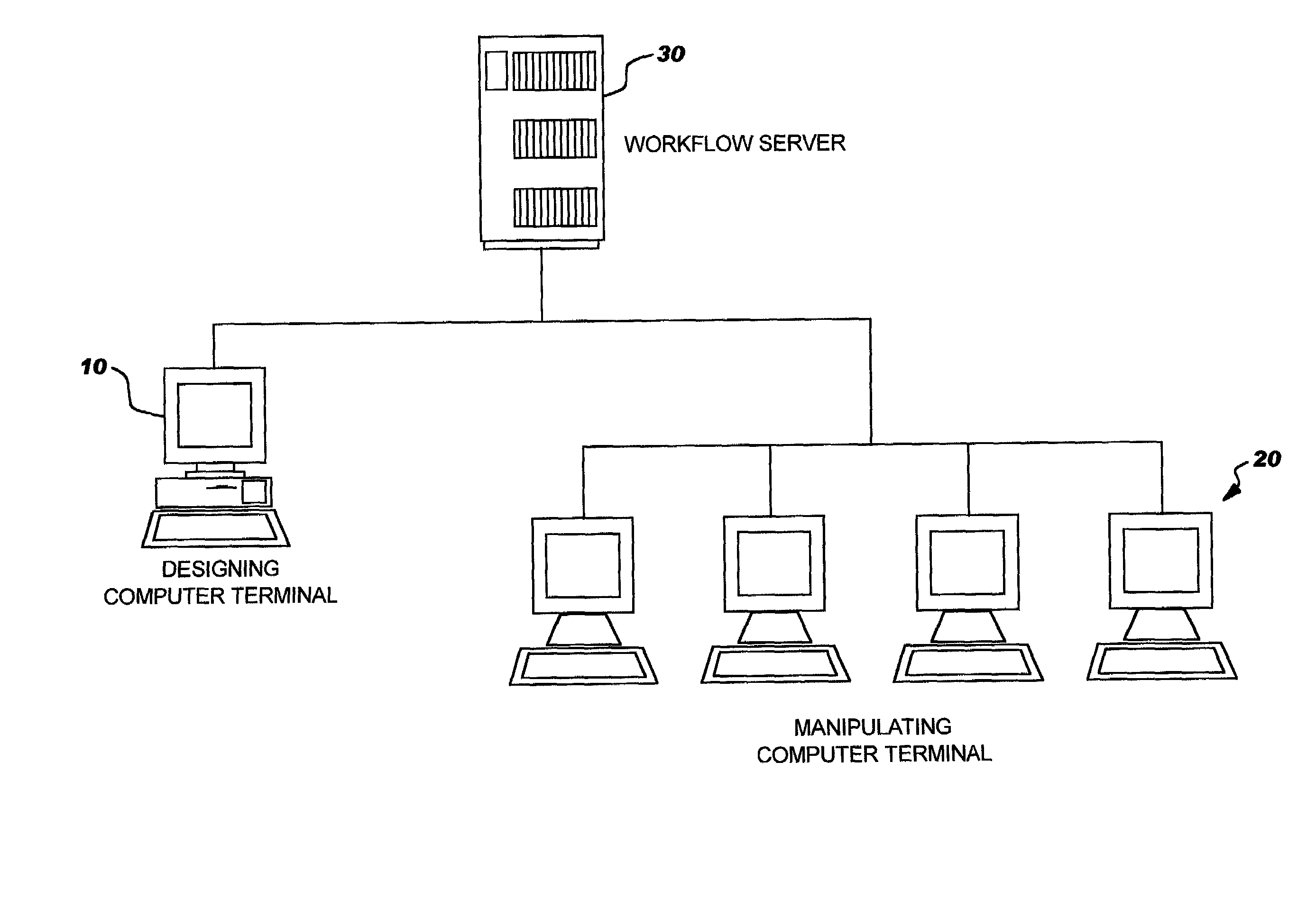
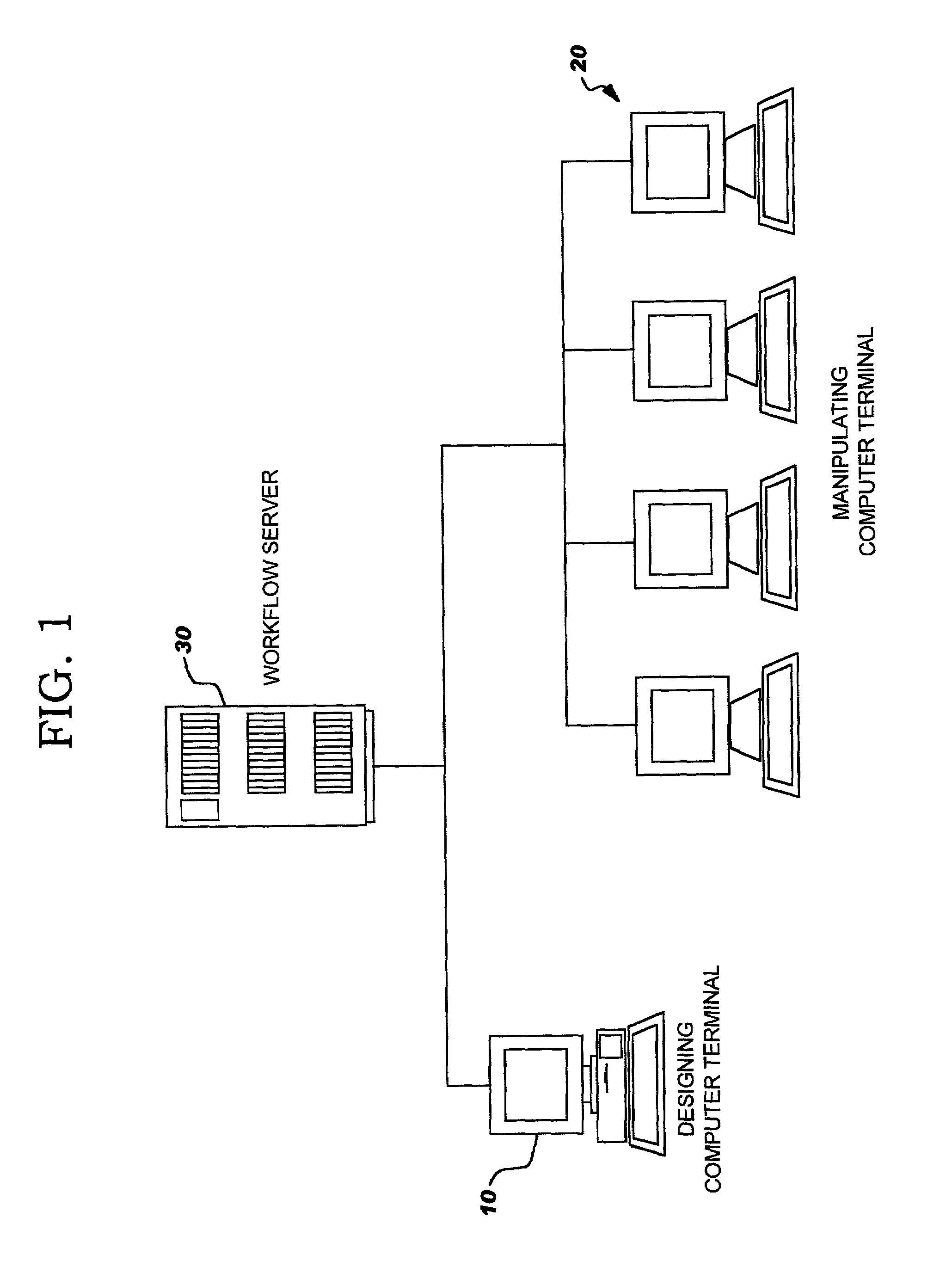
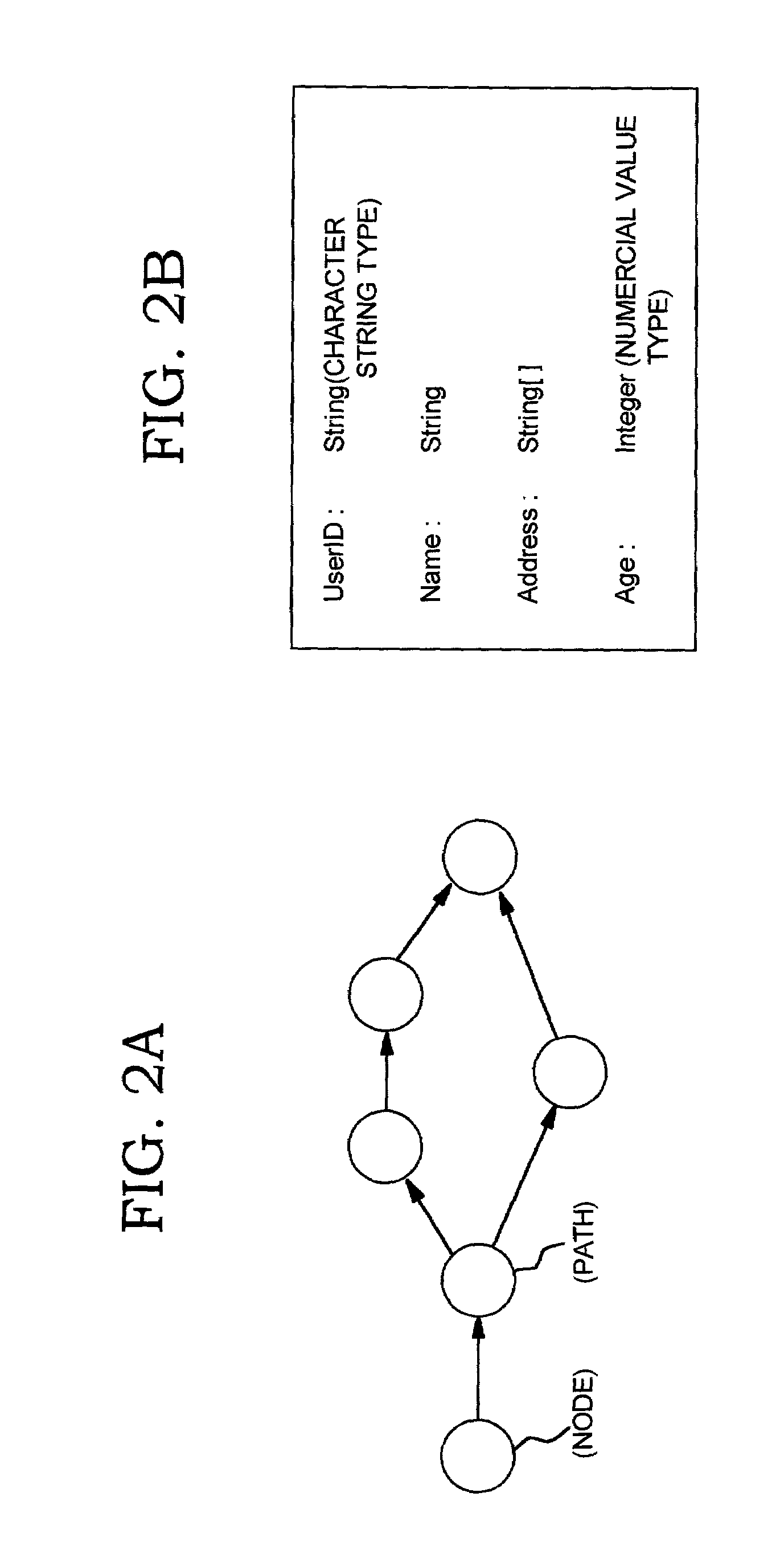
[0050]A workflow definition refers to a definition that includes a plurality of nodes and paths for connecting the nodes.

[0051]Node:

[0052]A node refers to a unit of an operation definition included in the workflow definition. An actual operator and a data input screen are assigned to a node.

[0053]Data Definition:

[0054]A data definition refers to a definition of data which a process can set and refer to. The data definition defines a data name, a data type, or a data array. The data type includes a character string type and a numerical value type.

[0055]Data Attribute Definition:

[0056]A data attribute definition refers to a definition of an attribute for limiting a value of data and forms a part of the data definition. The attribute of character...


PUM


Abstract

A workflow system for a paperless office, an information processing apparatus, a method for simply defining a complicated workflow, for example, a workflow such as a circulation among a plurality of departments where the circulation route varies in each department, and a storage medium. A workflow system comprises: a manipulating computer terminal for executing a workflow between persons in charge, a computer terminal for designing the workflow by designating project variables for multiplexing a plurality of paths for nodes, each indicating a unit of operation to be handled; and a workflow server for managing the designed workflow and accessing the manipulating computer terminals in accordance with activities that indicate operations assigned to the nodes.

Description

FIELD OF THE INVENTION[0001]The present invention relates to improvement of workflow in an office, and more particularly to a workflow system capable of dynamically changing a route.BACKGROUND[0002]Although a paperless form-processing system was first proposed some time ago, it cannot be said that paperless form-processing systems are in widespread use today, due to the complexity of slip processing, problems in handling exceptional processing, and the like. To computerize a large number of slips requires a simple way of defining forms and routes, and a flexible routing function for implementing an approval system.[0003]Related work is disclosed in the gazettes of Japanese Patent Laid-Open Nos. Hei 10(1998)-49603, Hei 10(1998)-177610 and Hei 5(1993)-216736, for example. The gazette of Japanese Patent Laid-Open No. Hei 10(1998)-49603 discloses a technique for preventing leakage of confidential information in the following manner. When data is circulated from a process A to a differen...

Claims


Application Information

Patent Timeline
Patent Type & Authority Patents(United States)
IPC IPC(8): G06F15/173G06Q10/00G06Q10/06G06Q50/00
CPCG06Q10/10
Inventor OHSAKI, HIROYASUTSUDA, KAZUYUKI
Owner IBM CORP
Learn More