Virtual work flow management method

a virtual work flow and work flow management technology, applied in the field of virtual work flow management methods, can solve the problems of reducing affecting the efficiency of the company, so as to reduce the number of workflow definitions and reduce the number of maintenance steps

Inactive Publication Date: 2006-01-10
HITACHI LTD
View PDF6 Cites 77 Cited by
  • Summary
  • Abstract
  • Description
  • Claims
  • Application Information

AI Technical Summary

Benefits of technology

[0022]According to the invention, through the use of the virtual workflow definition, in the case of transferring the workflow with an outside company, no association is executed directly by using the actual workflow definition. It is thus necessary to reduce the number of the maintenance steps without having to notify the outside of the change if the internal procedure is changed.
[0023]According to the invention, by linking only the node of the actual workflow definition required for the progress information with the node of the virtual workflow definition, it is possible to notify the other party of the necessary progressing information as protecting the procedure information inside of the company fro

Problems solved by technology

However, the foregoing background arts have the problems to be discussed below.
Second, the workflow managing system has difficulty in disclosing the necessary information to an outside domain as keeping the exact progressing information.
Hence, if the domain of the other party is located outside of the company, the information inside of the company may be leaked outside.
This is unfavorable to the security.
Hence, this system needs to do a troublesome work in notifying the sender domains of the workflow definition for each service.
Fourth, in the

Method used


Image

  • Virtual work flow management method
  • Virtual work flow management method
  • Virtual work flow management method

Examples


Embodiment Construction

[0041]Hereafter, one embodiment of the present invention will be described in detail with reference to the appended drawings.

[0042](Example of Virtual Workflow Definition)

[0043]At first, the description will be oriented to an example of the virtual workflow definition.

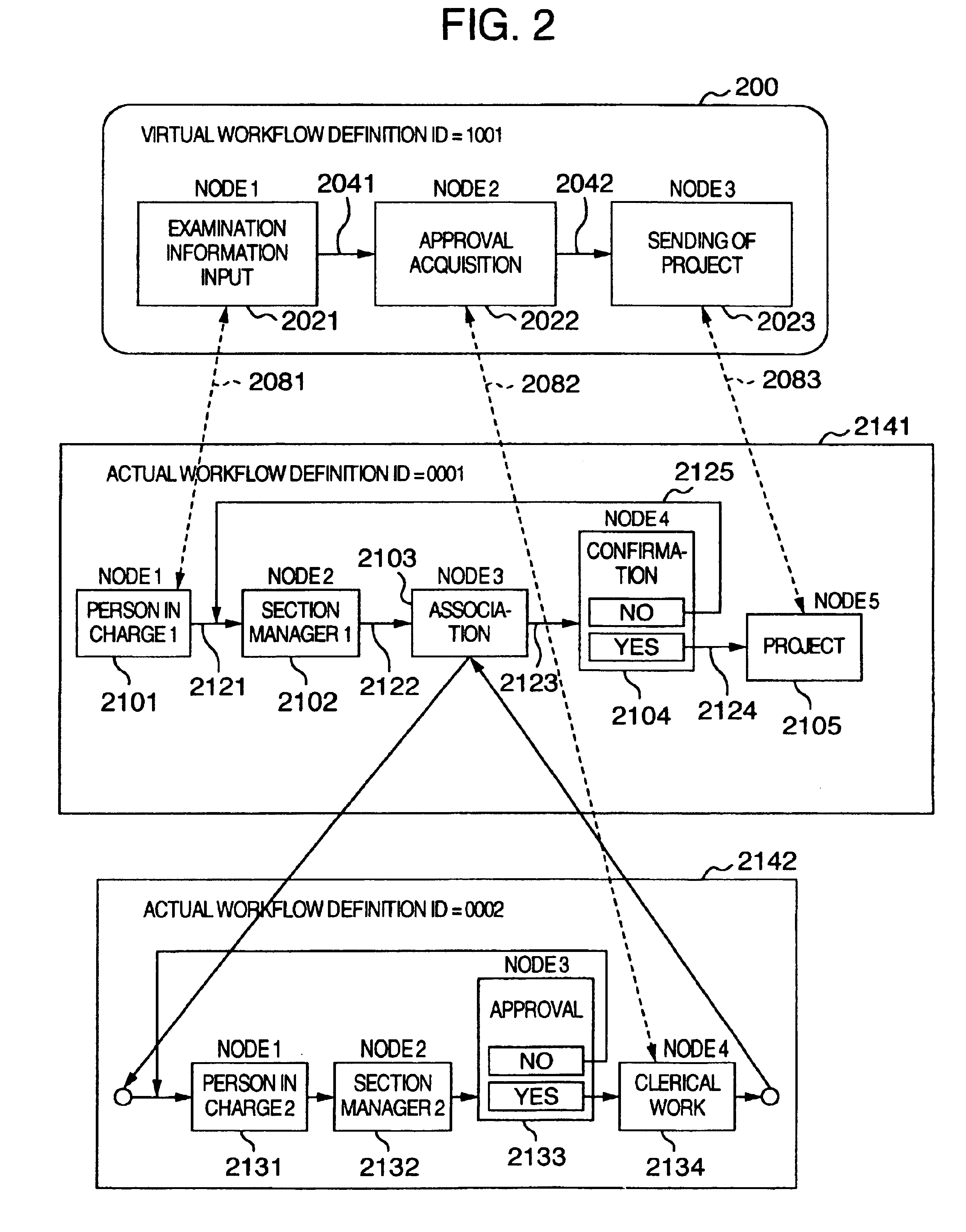
[0044]FIG. 2 shows an example of a virtual workflow definition and an actual workflow definition used in the embodiment.

[0045]As shown in FIG. 2, a virtual workflow definition 200 is intended for a user and is composed of virtual workflow nodes 2021 to 2023, arcs 2041 and 2042, and definition links 2081 and 2082 (to be connected with actual workflow definitions 2141 and 2142). Each of the virtual workflow nodes 2021 to 2023 represents one step in the virtual workflow definition 200. The arcs 2041 and 2042 serve to connect the node 2021 with the other node 2022 and the node 2022 with the other node 2023, respectively. The process at each step proceeds toward the arrow of each of the arcs 2041 and 2042.

[0046]The actual w...


PUM


Abstract

A processing node is selected from an actual workflow definition composed of the corresponding processing nodes to an actual service flow according to the purpose of use of a client. A virtual workflow definition composed of the virtual node corresponding to the selected processing node is created by a server and displayed on a screen of the client. A link is set for indicating correspondence between the virtual node of the virtual workflow and the processing node of the actual workflow. When an inquiry about the progressing state of the virtual workflow is given from a client, the server searches the processing node being current executed from the actual workflow. If the processing node does not have any link, the server tracks back the processing nodes on the actual workflow for searching the processing node having the link and an access right given from the client and then reply the progressing state of the processing node as the progress information of the virtual workflow to the client.

Description

BACKGROUND OF THE INVENTION[0001]The present invention relates to a workflow system for managing an overall work through the use of a plurality of workflow definitions.[0002]A representative example of a conventional workflow system arranged to utilize a plurality of workflow definitions is described in JP-A-8-123744. This workflow system implements the association or the serial association of workflows by combining a plurality of workflow definitions in a hierarchical or serial manner. This workflow system is arranged to provide an inlet and an outlet for the workflow definition and linking the inlet of one workflow definition with the outlet of another workflow definition. This system therefore enables to manage the workflow definition across two or more sections independently in each section.[0003]Further, another example of the workflow system provided with means for grasping the progressing state of the flow being executed in the outside workflow system such as another organiza...

Claims


Application Information

Patent Timeline
IPC IPC(8): G06F9/46G06F13/00G06Q10/00G06Q10/06G06Q10/10G06Q50/00
CPCG06Q10/10G06Q10/0633
Inventor SAKAGUCHI, TOSHIAKIAKIFUJI, SHUNSUKETAMAKI, MASATO
Owner HITACHI LTD
Why Eureka
Try Eureka