
Method and apparatus for determining downhole pressures during a drilling operation

a technology of pressure measurement and drilling operation, which is applied in the field of determining downhole parameters, can solve the problems of consuming significant amounts of rig time and limited patents, and achieve the effect of facilitating data collection and/or communication

Active Publication Date: 2006-01-17
SCHLUMBERGER TECH CORP
View PDF46 Cites 88 Cited by
  • Summary
  • Abstract
  • Description
  • Claims
  • Application Information

AI Technical Summary

Benefits of technology

[0015]Other aspects of the invention will be clear from the description provided herein.

Problems solved by technology

Each of these patents is limited in that the formation testing tools described therein are only capable of acquiring formation data as long as the wireline tools are disposed in the wellbore and in physical contact with the formation zone of interest.
Since “tripping the well” to use such formation testers consumes significant amounts of expensive rig time, it is typically done under circumstances where the formation data is absolutely needed, when tripping of the drill string is done for a drill bit change or for other reasons.

Method used


Image

  • Method and apparatus for determining downhole pressures during a drilling operation
  • Method and apparatus for determining downhole pressures during a drilling operation
  • Method and apparatus for determining downhole pressures during a drilling operation

Examples


Embodiment Construction

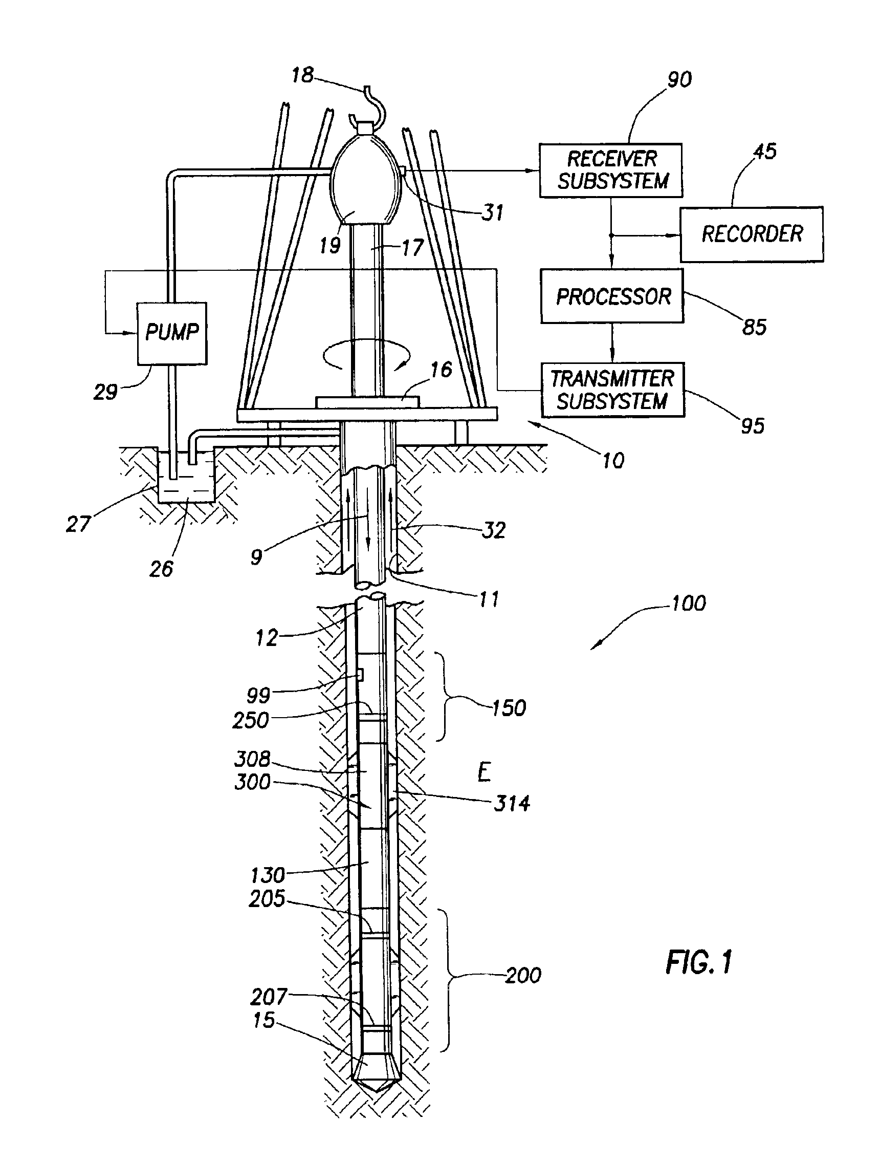
[0025]FIG. 1 shows a typical drilling system and related environment. Land-based platform and derrick assembly 10 are positioned over wellbore 11 penetrating subsurface formation F. Wellbore 11 is formed by rotary drilling in a manner that is well known. Those of ordinary skill in the art given the benefit of this disclosure will appreciate, however, that the present invention also finds application in directional drilling applications as well as rotary drilling, and is not limited to land-based rigs.

[0026]Drill string 12 is suspended within wellbore 11 and includes drill bit 15 at its lower end. Drill string 12 is rotated by rotary table 16, energized by means not shown, which engages kelly 17 at the upper end of the drill string. Drill string 12 is suspended from hook 18, attached to a traveling block (also not shown), through kelly 17 and rotary swivel 19 which permits rotation of the drill string relative to the hook.

[0027]Drilling fluid or mud 26 is stored in pit 27 formed at t...


PUM


Abstract

A method and apparatus is provided to collect downhole data during a drilling operation via a downhole tool. A differential pressure is created by the difference between internal pressure of fluid passing through the downhole tool and the annular pressure in the wellbore. The apparatus includes a drill collar connectable to the downhole drilling, and has an opening extending into a chamber therein. A piston is positioned in the chamber and has a rod extending into the opening. The piston is movable between a closed position with the rod filling the opening, and an open position with the rod retracted into the chamber to form a cavity for receiving downhole fluid. A sensor is positioned in the rod for collecting data from fluid in the cavity. The apparatus may also be provided with a probe and / or hydraulic circuitry to facilitate the collection of data.

Description

BACKGROUND OF INVENTION[0001]1. Field of the Invention[0002]This invention relates generally to the determination of various downhole parameters in a subsurface formation penetrated by a wellbore. More particularly, this invention relates to the determination downhole parameters, such as annular, formation and / or pore pressure, during a drilling operation.[0003]2. Description of the Related Art[0004]Present day oil well operation and production involves continuous monitoring of various subsurface formation parameters. One aspect of standard formation evaluation is concerned with the parameters of reservoir pressure and the permeability of the reservoir rock formation. Continuous monitoring of parameters such as reservoir pressure and permeability indicate the formation pressure change over a period of time, and is essential to predict the production capacity and lifetime of a subsurface formation.[0005]Present day operations typically obtain these parameters through wireline logging...

Claims


Application Information

Patent Timeline
Patent Type & Authority Patents(United States)
IPC IPC(8): E21B47/06E21B21/08E21B49/08E21B49/10
CPCE21B49/10E21B21/08
Inventor CIGLENEC, REINHARTHOEFEL, ALBERT
Owner SCHLUMBERGER TECH CORP
Features
  • Generate Ideas
  • Intellectual Property
  • Life Sciences
  • Materials
  • Tech Scout
  • Unparalleled Data Quality
  • Higher Quality Content
  • 60% Fewer Hallucinations
Learn More