Apparatus for detecting fuel-vapor gas leaks, and vent valve apparatus applied to this apparatus

a technology for detecting fuel-vapor gas leaks and vent valves, applied in the direction of instruments, fluid-tightness measurement, combustion-air/fuel-air treatment, etc., can solve the problems of limiting the precision of judgment, complex configuration, and unpleasant sounds

Inactive Publication Date: 2006-01-17
MITSUBISHI ELECTRIC CORP
View PDF9 Cites 30 Cited by
  • Summary
  • Abstract
  • Description
  • Claims
  • Application Information

AI Technical Summary

Benefits of technology

[0006]The present invention has been made in order to solve the above problems, and aims at providing a fuel-vapor gas leak detection device that can accurately detect leakage, even when an internal combustion engine is running.

Problems solved by technology

Since the conventional apparatus for detecting fuel-vapor gas leaks are configured for driving the air pump and supplying the pressurized air to the purge line and the fuel tank after the internal combustion engine is halted, and for judging the leakage amount according to the operating current of the air pump drive motor, the air pump, the drive motor and peripheral pipes are needed and the configuration is complex.
Since internal pressure of the purge line and the fuel tank are indirectly measured according to the operating current of the air pump drive motor, there is a limit to the precision of the judgment.
Moreover, it is necessary to operate the air pump until a predetermined internal pressure is obtained, since there are problems that battery will consume in the leak detection operation after the internal combustion engine is halted; and that unpleasant sounds are given by the leak detection air pump operation.

Method used


Image

  • Apparatus for detecting fuel-vapor gas leaks, and vent valve apparatus applied to this apparatus
  • Apparatus for detecting fuel-vapor gas leaks, and vent valve apparatus applied to this apparatus
  • Apparatus for detecting fuel-vapor gas leaks, and vent valve apparatus applied to this apparatus

Examples


embodiment 1

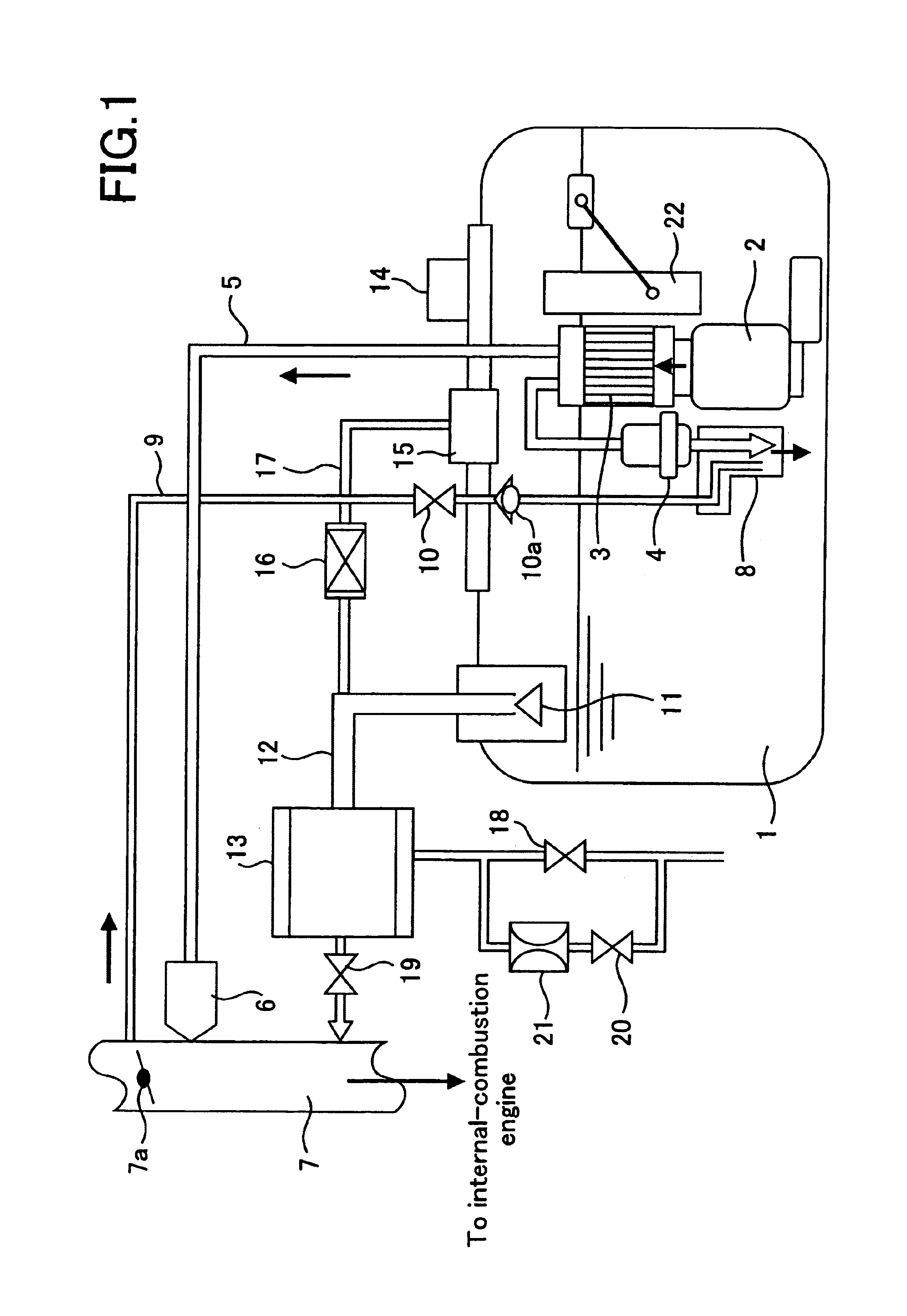
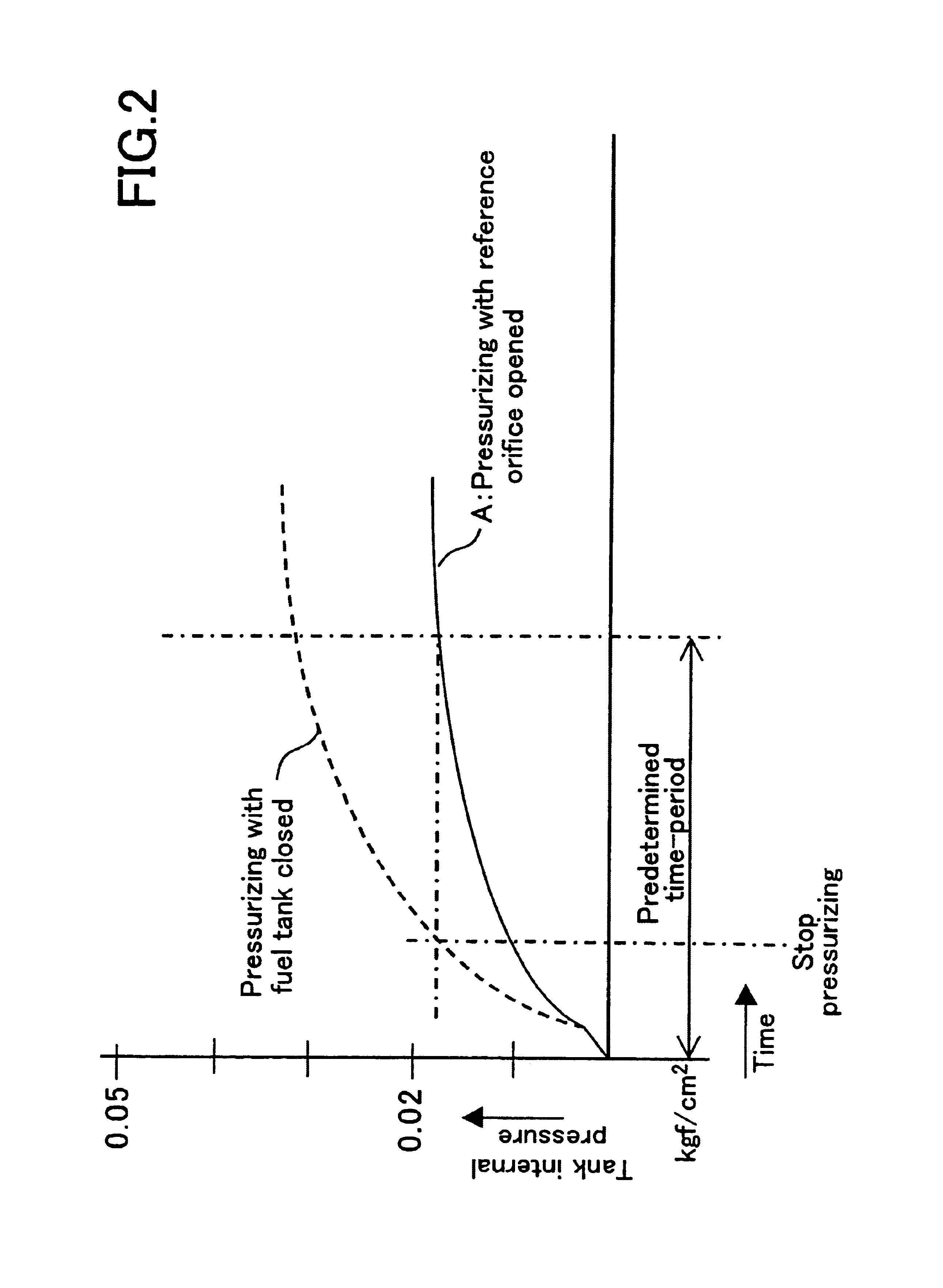
[0018]FIG. 1 is a block diagram of an apparatus for detecting fuel-vapor gas leaks according to Embodiment 1 of the invention; FIG. 2 illustrates an example of an initial curve according to Embodiment 1; and FIG. 3 is a graph illustrating how fuel tank internal pressure rises according to change in a fuel tank empty-space volume.

[0019]In FIG. 1, gasoline, which is fed from a submerged fuel pump 2 in the fuel tank 1, is filtered by a fuel filter 3; the gasoline pressure is regulated by a pressure regulator 4, and the gasoline is sent to an injector 6 through a fuel pipe 5; the gasoline is injected from the injector 6 to an intake-manifold 7 and is burned in an internal combustion engine. A jet pump 8, which serves as a jet pump for the fuel tank 1, is provided at an exhaust port of the pressure regulator 4, which branches off the fuel pipe 5. One end of an air-intake pipe 9 is connected to this jet pump 8, and the other end of the air-intake pipe 9 leads through a check-valve 10a and...

embodiment 2

[0041]FIG. 4 is a block diagram of the apparatus for detecting fuel-vapor gas leaks of Embodiment 2 of the invention, and FIG. 5 illustrates an example of an initial curve according to Embodiment 2.

[0042]In FIG. 4, reference numerals that are the same as in Embodiment 1 refer to identical items. A bypass valve 24 and a reference orifice 25 are arranged to bypass the bi-direction valve 16 of the fuel-vapor gas pathway 17. The reference orifice 25 has a 0.5 mm reference leak hole. The other end of the air-intake pipe 9, which is connected to the jet pump 8, leads to the atmosphere via the canister 13 through the control valve 10. A solenoid 32 is provided on the vent valve 11, and open / close control of the fuel tank 1 and the vent pipe 12 is carried out by external signals to the solenoid 32.

[0043]The solenoid 32, the control valve 10, the A-valve 18, the B-valve 19, the bypass valve 24, the internal pressure sensor 14, and the fuel level gauge 22 are connected to the CPU of the fuel ...

embodiment 3

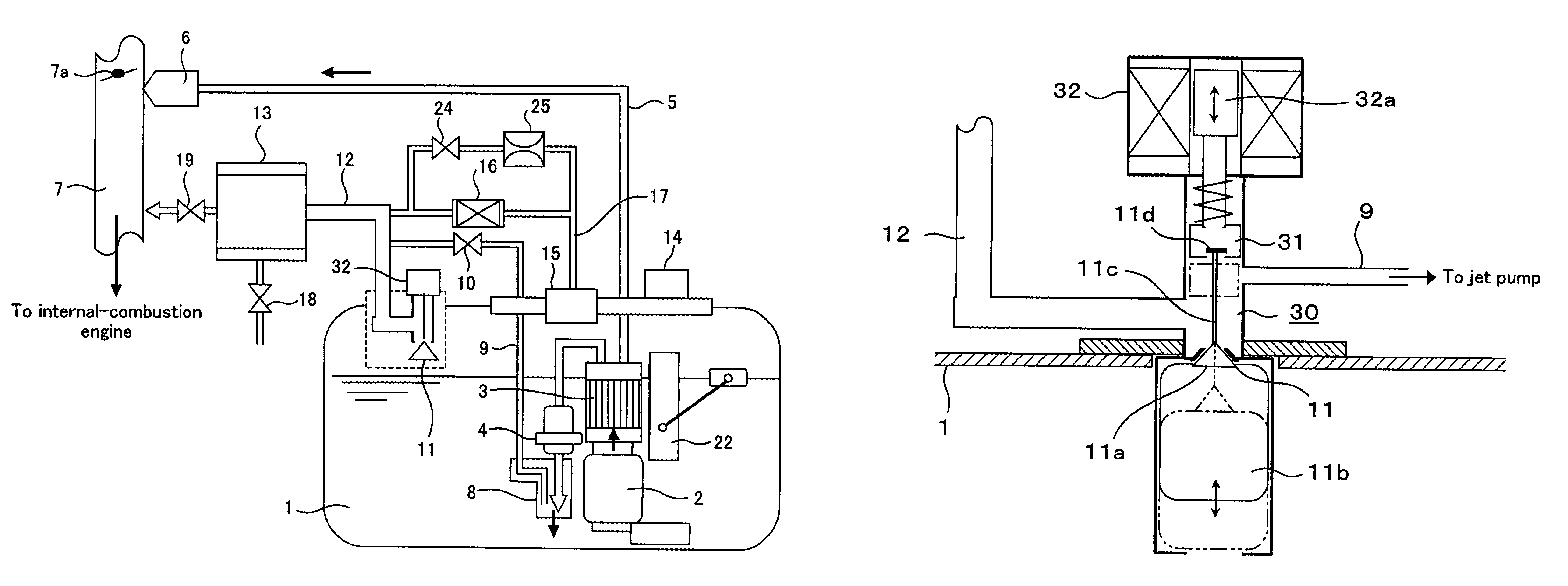
[0064]FIG. 6 is a block diagram of the apparatus for detecting fuel-vapor gas leaks of Embodiment 3 of the invention, and FIG. 7 illustrates a configuration of a vent valve device for Embodiment 3. In FIG. 6, reference numerals that are the same as in Embodiment 1 refer to identical items.

[0065]The vent valve 11, the control valve 10, a control valve body 31, and the solenoid 32, etc., are arranged as a unit in a vent valve device 30. The end of the intake gas pipe 9 that extends to the jet pump 8 is connected to the control valve 10 of vent valve device 30. The control valve 10 leads to the external atmosphere via the vent pipe 12 and the canister 13, and the control valve body 31 is driven by an external signal to the solenoid 32 to control the opening / closing to operate the control valve 10.

[0066]The vent valve device 30 will be explained here. In FIG. 7, the vent valve 11 is arranged so that a stopcock 11a operates together with a float 11b, and the stopcock 11a shuts off the fu...


PUM


Abstract

An apparatus for detecting fuel-vapor gas leaks that includes a jet pump (8) that introduces outside air into and pressurizes a vapor purge system including a fuel tank (1) by gasoline flow from a fuel pump (2); an internal pressure sensor (14) for measuring vapor purge system internal pressure, an open / close controllable reference orifice (21) that causes leakage through a reference leak hole; and a storage device for storing as an initial curve pressure changes during pressurization by the jet pump (8) for a predetermined time period, with the reference orifice (21) alone opened. The device can accurately detect leakage even while an internal combustion engine is running because it judges leak presence / absence by comparing a time series in a pressure curve obtained by jet pump (8) pressurization over the predetermined time period while idling with the vapor purge system completely shut-off, with a time series in the initial curve.

Description

BACKGROUND OF THE INVENTION[0001]1. Field of the Invention[0002]The present invention relates to apparatus for detecting fuel-vapor gas leaks in vehicle internal combustion engines.[0003]2. Description of the Related Art[0004]Conventional apparatus for detecting fuel-vapor gas leaks are disclosed in Japanese Laid-Open Patent Publication 2001-12319 and U.S. Pat. No. 6,112,728. Japanese Laid-Open Patent Publication 2001-12319 (pages 2-6, FIG. 1), for example, discloses a configuration for supplying pressurized air to a purge line and a fuel tank by means of an air pump, after an internal combustion engine is halted, and for judging a leakage amount according to the operating current of the air pump drive motor.[0005]Since the conventional apparatus for detecting fuel-vapor gas leaks are configured for driving the air pump and supplying the pressurized air to the purge line and the fuel tank after the internal combustion engine is halted, and for judging the leakage amount according to...

Claims


Application Information

Patent Timeline
Patent Type & Authority Patents(United States)
IPC IPC(8): F02M37/00B60K15/035F02M25/08
CPCF02M25/0818Y10T137/87217Y10T137/86678
Inventor MITANI, TATEKITSUTSUI, SEIJIKANAMARU, SHIGEKIYOSHIOKA, HIROSHI
Owner MITSUBISHI ELECTRIC CORP
Why Eureka
Try Eureka