
Electronic device enclosure with rotationally locked body and header

a technology for electronic devices and enclosures, applied in the direction of magnetic/electric field screening, cable junctions, transient suppressor details, etc., can solve the problems of failure of the device, high maintenance cost, and high scrap rate, and achieve the effect of preventing the relative rotation of the two parts

Active Publication Date: 2006-01-17
PPC BROADBAND INC
View PDF23 Cites 14 Cited by
  • Summary
  • Abstract
  • Description
  • Claims
  • Application Information

AI Technical Summary

Benefits of technology

This solution effectively locks the body and header in place, preventing rotation and longitudinal separation, reducing maintenance costs and scrap rates by eliminating the need for inductive soldering and ensuring reliable assembly.

Problems solved by technology

This torque is often great enough to cause rotation of the header relative to the body, resulting in failure of the device.
Such arrangements, although they may rotationally lock the header and outer sleeve, do not ensure that the header and body will not rotate relative to one another.
The many uncontrollable variables make the soldering process very unstable, resulting in high maintenance cost as well as higher scrap rates.
Furthermore, spare parts must be stocked for the soldering equipment, creating an additional expense, as does the power required to operate the equipment.

Method used


Image

  • Electronic device enclosure with rotationally locked body and header
  • Electronic device enclosure with rotationally locked body and header
  • Electronic device enclosure with rotationally locked body and header

Examples


first embodiment

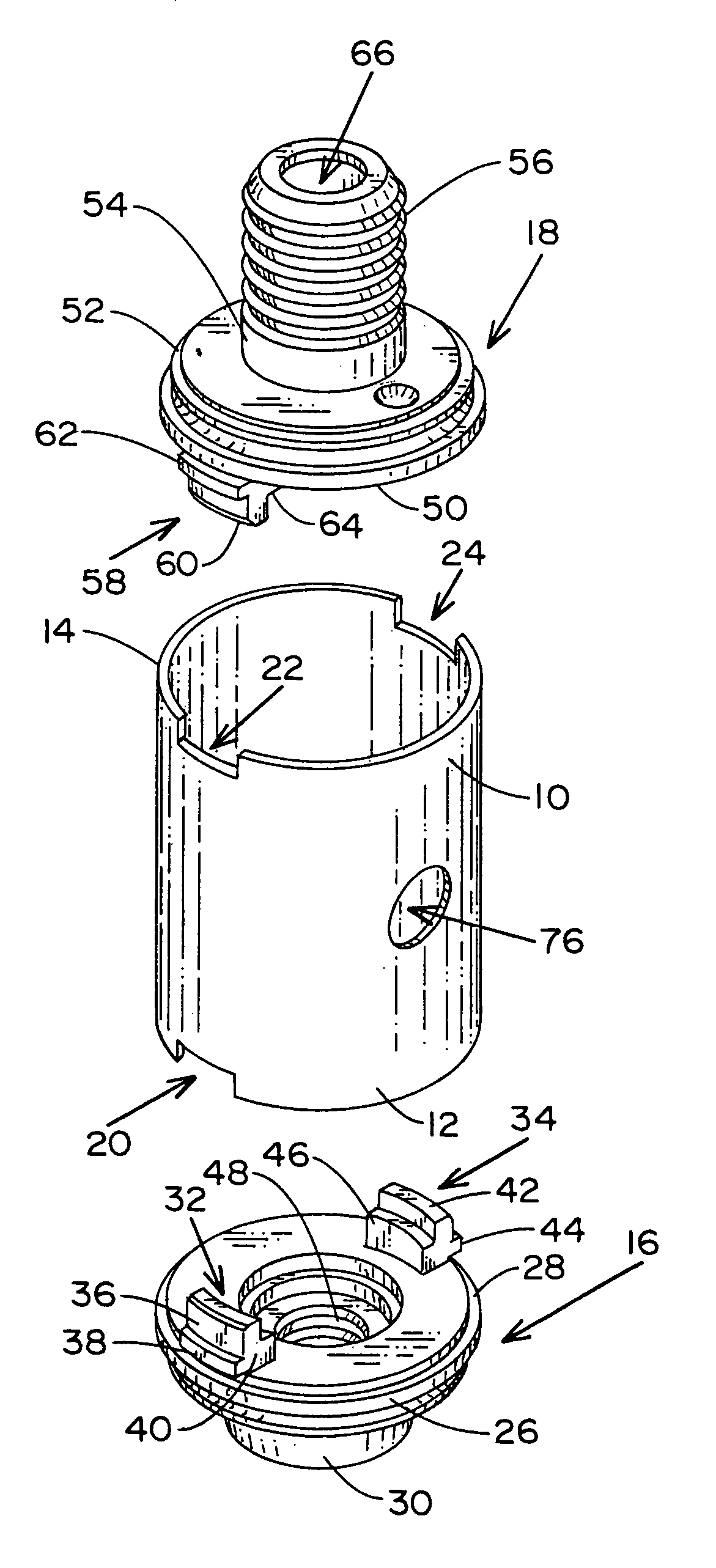
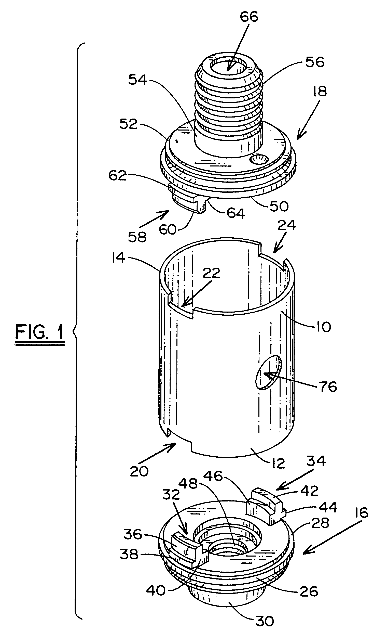
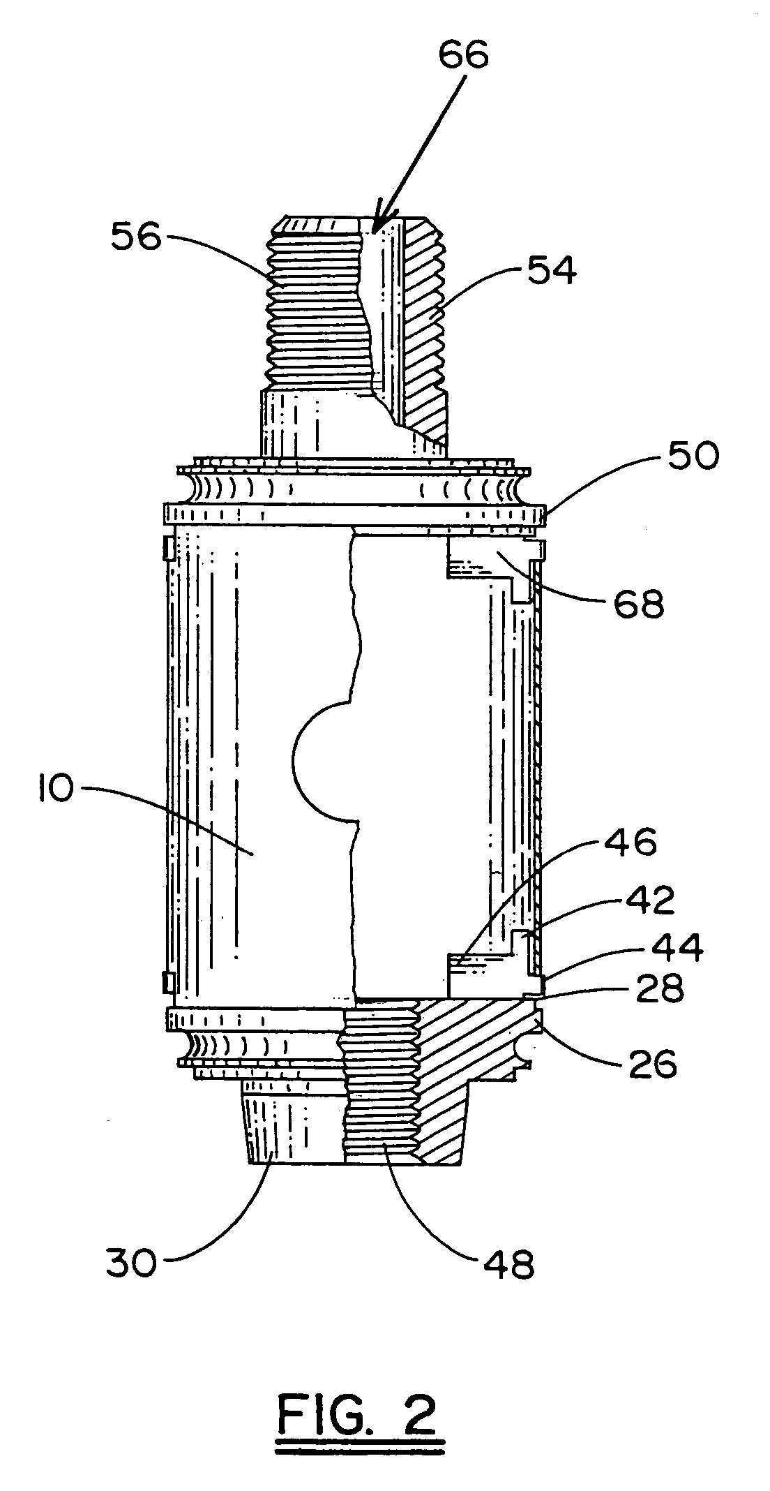
[0019]Referring now to the drawings, in FIGS. 1–3 is shown elements of an enclosure for an electronic device such as an RF trap for use in CATV applications. The elements shown in FIGS. 1 and 2 consist of a hollow, cylindrical body 10 having opposite ends 12 and 14 in parallel planes, male header 16 and female header 18. Notch 20 and a corresponding notch on the diametrically opposite side (not seen in FIG. 1) are cut into the wall of body 10 on opposite sides of end 12, and notches 22 and 24 are cut into the body wall on opposite sides of end 14.

[0020]Male header 16 includes central, annular portion 26 having a diameter substantially equal to the outer diameter of body 10, and annular portion 28 having a diameter substantially equal to the inner diameter of body 10. Stem portion 30 extends from one side of male header 16 and diametrically opposed tabs 32 and 34 extend from the other side, i.e., the said facing body 10. Tab 32 includes central portion 36, outer portion 38 and inner ...

second embodiment

[0023]Turning now to FIGS. 4–7, the invention is shown in a This is a six-pole device including male and female headers 78 and 80, which are identical to headers 16 and 18, respectively, of the previous embodiment. However, instead of one body member, open and notched at both ends, the present embodiment includes three body portions, termed first, second and third body portions and numbered 82, 84 and 86, respectively. First body portion 82 includes notches 88 and 90 extending into the body wall from end 92. Notch 94, and a diametrically opposite slot not seen in FIG. 4, extends into open end 96 of second body portion 84, the other end being closed by wall 98, having openings 100. Third body portion 86 includes notch 102, and a corresponding notch on the opposite side, extending into open end 104; wall 106, having openings 108, closes the other end of body portion 86. Opening 108 is used not only for inserting a tuning tool, but also for inserting potting (conformal) material which...


PUM


Abstract

An assembly for housing electronic components for use in a CATV system. The assembly includes a hollow body member having a central axis and opposite ends, at least one header adjoining one end of the body member in coaxial relation. The body member includes a notch in one end and the header includes a tab configured to extend into the notch to rotationally lock the body member to the header. The assembly may also include a plurality of hollow body members and a pair of headers each having a central axis. The body members and headers are positioned in an axially aligned array with the headers at opposite ends. The assembly includes cooperative structure rotationally locking each of the body members and headers to the adjacent body member and header. The assembly may further include a sleeve covering at least portions of the body member and headers.

Description

BACKGROUND OF THE INVENTION[0001]The present invention relates to enclosures for electronic devices, and more particularly to enclosures having one or more hollow, cylindrical body portions with a header on one or both ends used in cable television (CATV) applications.[0002]Coaxial cable devices such as RF filters mounted upon circuit boards are commonly housed in cylindrical enclosures having so-called body and header portions. When the device is installed in the field, the installer typically used a wrench to connect and tighten the adjoining connector, thereby applying a torque to the header. This torque is often great enough to cause rotation of the header relative to the body, resulting in failure of the device. Prior attempts to address this problem have included providing flat (i.e., linear) sides on the otherwise circular header which mate with flat sides on the interior of one end of an outer sleeve surrounding both the body and header. Such arrangements, although they may ...

Claims


Application Information

Patent Timeline
Patent Type & Authority Patents(United States)
IPC IPC(8): H01R12/00H05K9/00
CPCH05K9/0066
Inventor BENSON, ROBERTPIXLEY, HENRYZRAIK, SOUHEIL
Owner PPC BROADBAND INC
Learn More