Internal structure for connector with coil positioning seats

a technology of positioning seats and connectors, which is applied in the direction of coupling devices, two-part coupling devices, electrical devices, etc., can solve the problems of unstable feature of an article, difficult connection of the eight coils with the circuit board, and latent quality blemishes, etc., to save work hours, easy to mount, and easy to be fixed

Inactive Publication Date: 2006-01-17
SUPERWORLD ELECTRONICS
View PDF14 Cites 38 Cited by
  • Summary
  • Abstract
  • Description
  • Claims
  • Application Information

AI Technical Summary

Benefits of technology

[0011]The main object of the present invention is to provide an internal structure of a connector with at least a coil positioning seat, each coil can be easily mounted in a nest of a coil positioning seat, and each coil is effectively isolated to surely get an effect of protection.
[0012]Another object of the present invention is to provide an internal structure of a connector with at least a coil positioning seat; by having a first and a second circuit board both perpendicular to a lateral connecting board and two positioning seats allocated between the first and the second circuit boards, the internal structure basically has a cubic contour, and is very easily to be fixed on the lateral connecting board, this can save much working hours and lower the cost of production.

Problems solved by technology

In a conventional internal structure, coils are randomly assembled on a printed circuit board in a floating sticking mode, such a mode of processing renders the lower ones of the coils to be not accurately positioned, thus the feature of an article resulted is unstable and it is worriable that there is latent quality blemish.
And one thing even more cumbersome, the work of connecting of the eight coils with the circuit board is quite difficult; assembling of a conventional technical structure must be done by a skillful technician to complete, it is time consuming and not benefit to production, thereby the conventional technical structure has to be improved.

Method used


Image

  • Internal structure for connector with coil positioning seats
  • Internal structure for connector with coil positioning seats
  • Internal structure for connector with coil positioning seats

Examples


Embodiment Construction

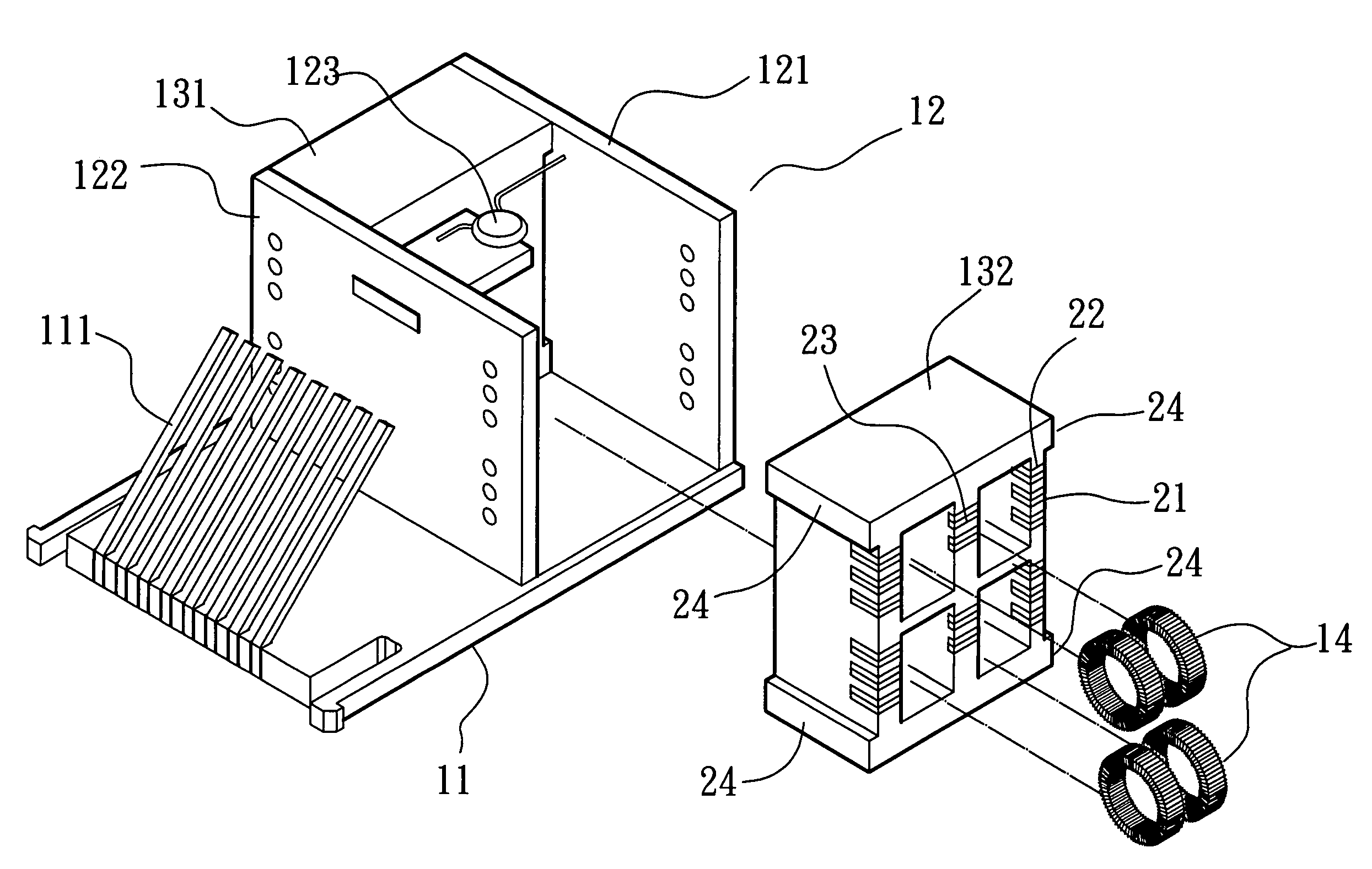
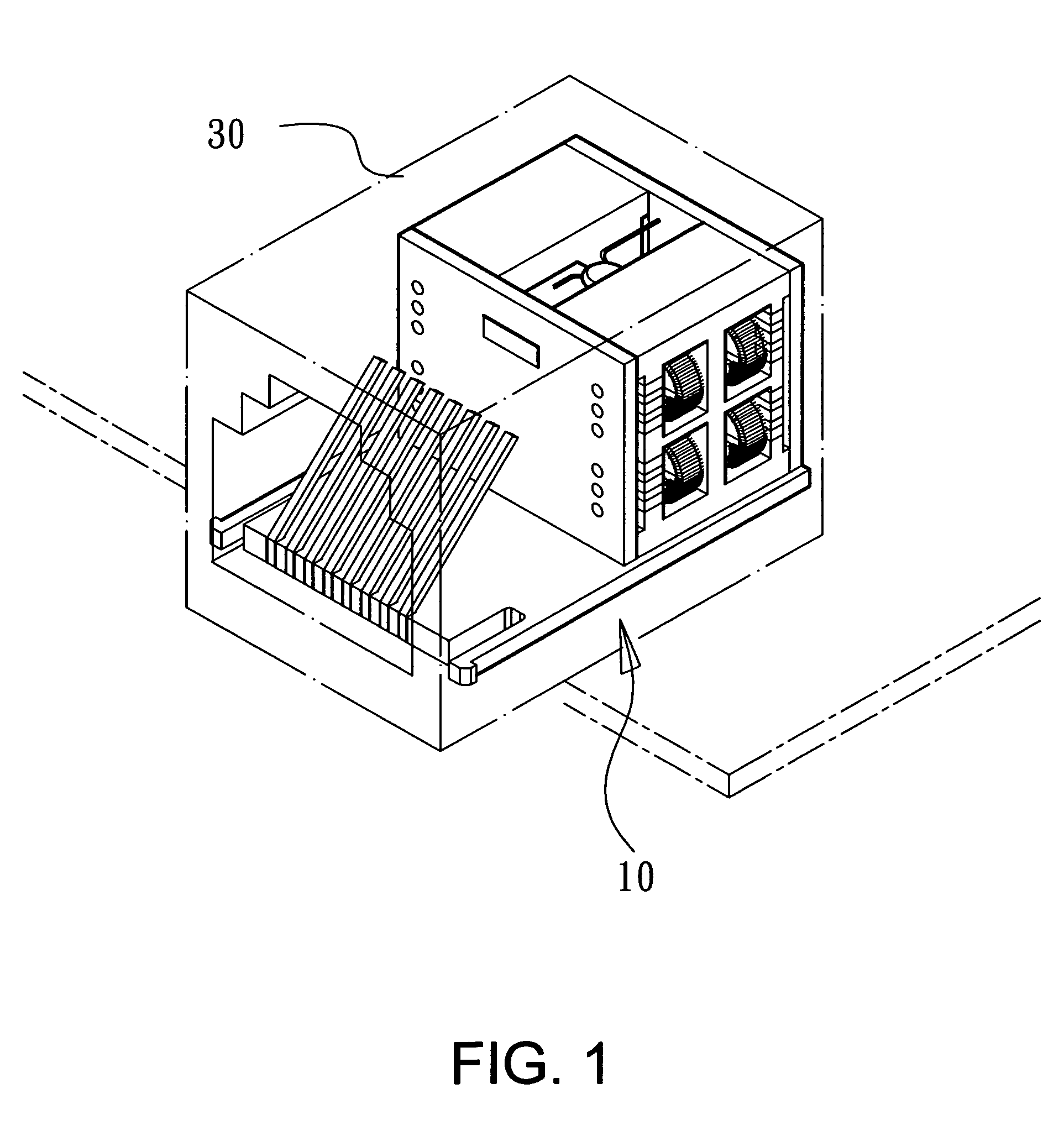
[0019]Referring to FIGS. 1–4 showing the arrangement of a nest-typed positioning seat, the connector used for the present invention has therein an internal structure 10 having a plurality of positioning seats to separate coils; the internal structure 10 is covered with a metallic housing 30 to form a communication connector.

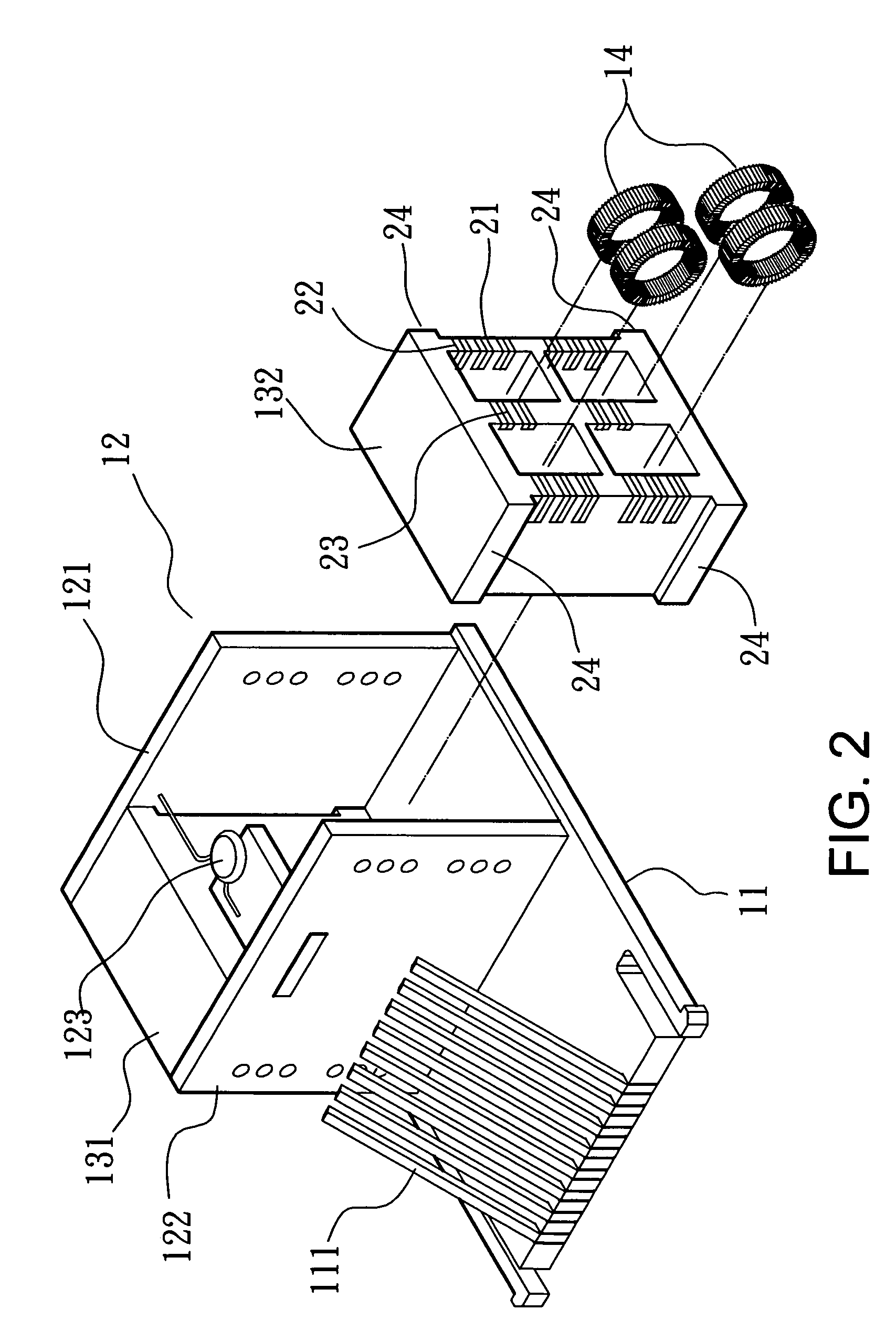
[0020]Referring to FIGS. 2–4, the internal structure 10 of the present invention mainly has a lateral connecting board 11 which is provided thereon in advance with a plurality of metallic guide pins (electrical contacts) 111; in a network-card connector such as RJ45 used at the present time, there are eight guide pins (electrical contacts) 111. The lateral connecting board 11 is provided thereon at one side of it with a circuit board assembly 12 having a resistance-capacitance (RC) element 123.

[0021]The circuit board assembly 12 is composed, in addition to the resistance-capacitance (RC) element 123, of a first circuit board 121 and a second circuit board 122. Th...


PUM


Abstract

An internal structure for a connector with at least a nest-typed positioning seat that is covered with a metallic housing to form a communication connector, and has a connecting board having thereon metallic guide pins and having thereon a circuit board assembly with a resistance-capacitance (RC) element and comprising a first and a second circuit board, each positioning seat is provided between the first and the second circuit boards for receiving coils; connecting lines of the coils are pulled to one side of the seat to connect the assembly, an object of connecting the coils with the circuit board assembly thus is easily attained. Each nest is provided on its periphery with slits of different depths, connecting lines of the coils can be extended through the slits to make electric connecting with the assembly. Thereby a function of wave filtering and abnormal voltage isolating is obtained.

Description

BACKGROUND OF THE INVENTION[0001]1. Field of the Invention[0002]The present invention is related to an internal structure of a connector with at least a coil positioning seat, and especially to an internal structure of a connector of which coils are received in the coil positioning seat to make easy of connection with a circuit board.[0003]2. Description of the Prior Art[0004]In the internal structure of an electric communication connector, a plurality of coils must be provided on an electric circuit board to get the function of wave filtering and abnormal voltage isolating. Particularly for the present time, eight pins in a high-speed communication connector will all be used, thereby there must be eight coils provided for each high-speed communication connector; the number of pins is larger than that requested before. In a conventional internal structure, coils are randomly assembled on a printed circuit board in a floating sticking mode, such a mode of processing renders the lower...

Claims


Application Information

Patent Timeline
Patent Type & Authority Patents(United States)
IPC IPC(8): H01R13/66
CPCH01R24/64H01R13/7197H01R13/6616H01R13/6625H01R13/6633
Inventor LIEN, WEN-FU
Owner SUPERWORLD ELECTRONICS
Why Eureka
Try Eureka