Continuously variable stepped transmission

a transmission and continuously variable technology, applied in the direction of gearing control, gearing elements, gearing, etc., can solve the problems of reducing the operating efficiency of the vehicle, frequent need for shifting, and affecting the operation efficiency of the engine, so as to reduce the need for shifting and reduce the torque. , the effect of restoring the torqu

Inactive Publication Date: 2006-01-17
EATON CORP
View PDF42 Cites 43 Cited by
  • Summary
  • Abstract
  • Description
  • Claims
  • Application Information

AI Technical Summary

Benefits of technology

[0005]The inventive system beneficially reduces the need for shifting by using the CVT to expand the operating range of each of the stepped gears in the automated gear unit. This is achieved in spite of the limited torque capacity of the CVT by subjecting the CVT to only a portion of the high torque levels of the engine. A step-down gear set reduces the torque passing through the CVT, and then passing the torque from the CVT through a step-up gear set which restores the torque. The CVT is further protected by splitting the torque from the engine, and recombining in a planetary gear set. The planetary gear set serves to mix or combine the direct torque element from the engine with the torque from the CVT.

Problems solved by technology

The large number of gears means that there is a frequent need for shifting.
However, even with a large number of ratios, and automated shifting, the engine speed varies with the speed of the vehicle when the vehicle is in a given gear ratio.
This means that the engine's operating parameters must be compromised to accommodate the anticipated range of engine operating speeds.
Shifting decreases the operating efficiency of the vehicle, as there can is typically a dip in vehicle speed during the shift when the engine is momentarily disconnected from the drive wheels, and a subsequent need to bring the vehicle back to its target speed.
One of the limitations to the use of CVTs has been their limited torque capacity.
However, given the high torque outputs of engines used for heavy duty trucks, and the limited torque capacities of know CVT systems, particularly CVT belt-type systems, further torque reduction was necessary.

Method used


Image

  • Continuously variable stepped transmission
  • Continuously variable stepped transmission
  • Continuously variable stepped transmission

Examples


Embodiment Construction

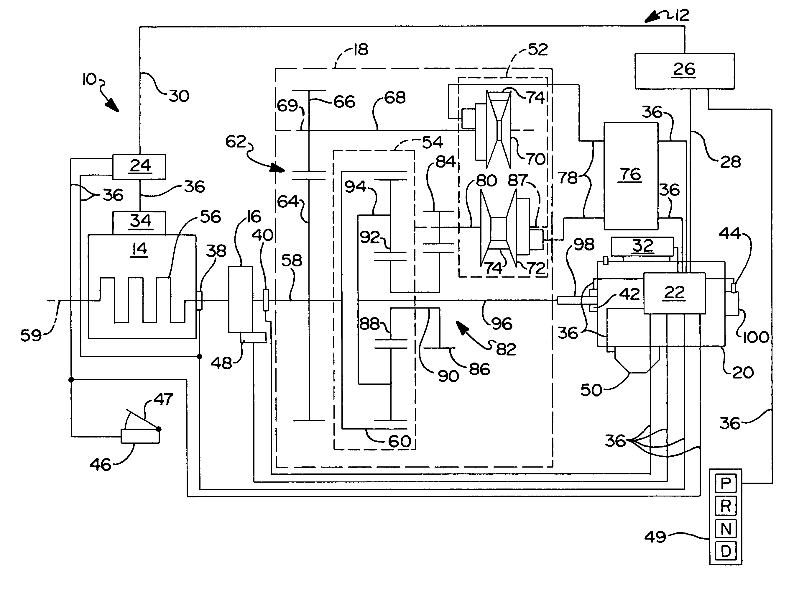
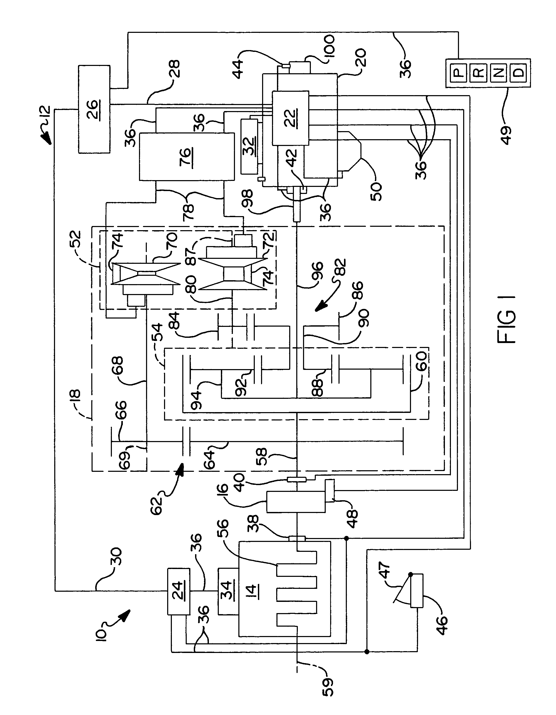
[0019]Referring to FIG. 1, a vehicle drivetrain 10 including a continuously variable transmission 12 and an electronically controlled internal combustion engine 14 is illustrated. Continuously variable transmission 12 is connected with engine 14 by a normally engaged master friction master clutch 16. Transmission 12 includes a CVT module 18 and an automated counter-shaft type mechanical transmission gear unit 20.

[0020]An exemplary gear unit 20 is of the type sold by Eaton Corporation, the assignee of this invention, under the name AutoShift®. A seven speed model (Model numbers TO-11607-ASX and TO-14607-ASX) is used as one exemplary embodiment of gear unit 20. Units or transmissions such as exemplary unit 20 are well known in the prior art and may be appreciated by reference to U.S. Pat. Nos. 3,105,395, 3,283,613 and 4,754,665, the disclosures of which are incorporated by reference. It should be appreciated that any transmission featuring a plurality of fixed gear ratios and automati...


PUM


Abstract

A continuously variable transmission for use with motor vehicles includes an ECU, an automated gear unit, a variator, an input gear set, an input fixed ratio element and an output fixed ratio element. The automated gear unit has multiple selectively engaged gear ratios and engages one of the gear ratios responsive to commands from the ECU. The variator varies a ratio of torque between its input and outout shafts responsive to commands from the ECU. The variator output shaft is connected to the gear unit input shaft. The input gear set is connected to the variator input shaft. The input fixed ratio element reduces torque from the input gear set to the variator, and is disposed between the input gear set and the variator input shaft. The output fixed ratio element increases the torque from the variator, and is disposed between the variator output shaft and the gear unit input shaft.

Description

RELATED APPLICATIONS[0001]This application claims the benefit of U.S. Provisional Application No. 60 / 423,085, filed Nov. 1, 2002 entitled “Continuously Variable Stepped Transmission”, which is incorporated herein by reference in its entirety.FIELD OF THE INVENTION[0002]The present invention relates to multi-speed transmissions used in combination with continuously variable transmissions or CVTs. In particular, the present invention relates to the use of a CVT between an engine and a multi-speed transmission.BACKGROUND OF THE INVENTION[0003]Trucks, particularly heavy duty trucks, commonly employ multiple speed counter-shaft type mechanical transmissions having up to at least 18 different torque multiplication ratios. The large number of ratios is needed to enable a fully loaded truck to perform a variety of necessary tasks, including low speed maneuvering in forward and reverse gears as required for moving about freight yards and for loading and unloading tasks, accelerating from a d...

Claims


Application Information

Patent Timeline
Patent Type & Authority Patents(United States)
IPC IPC(8): F16H37/02F16H37/08F16H61/662F16H61/686
CPCF16H37/0846F16H61/662F16H61/686F16H2037/088Y10T74/19051Y10T74/19023Y10T74/19074Y10T74/19079Y10T74/19056
Inventor MORSCHECK, TIMOTHY J.
Owner EATON CORP
Why Eureka
Try Eureka