Micro-electromechanical actuators

a micro-electromechanical and actuator technology, applied in the field of actuators, can solve the problems of electromagnetic actuators, complication of manufacturing processes, and difficulty in fine displacemen

Inactive Publication Date: 2006-01-17
ELECTRONICS & TELECOMM RES INST +1
View PDF10 Cites 13 Cited by
  • Summary
  • Abstract
  • Description
  • Claims
  • Application Information

AI Technical Summary

Problems solved by technology

The reason is that the electromagnetic-type actuator has many disadvantages such as complication of manufacturing process and difficulty of a fine displacement with its various advanta

Method used


Image

  • Micro-electromechanical actuators
  • Micro-electromechanical actuators
  • Micro-electromechanical actuators

Examples


Embodiment Construction

[0023]The present invention will be described in detail by way of a preferred embodiment with reference to accompanying drawings, in which like reference numerals are used to identify the same or similar parts.

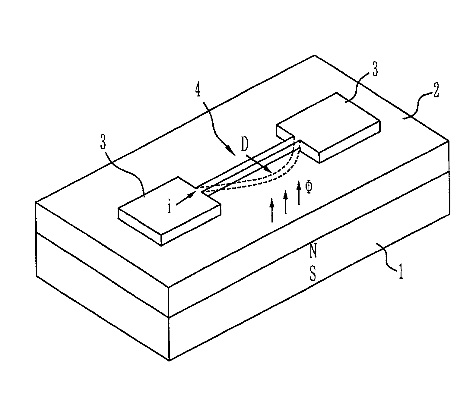
[0024]FIG. 1 shows an electromagnetic-type micro-electromechanical actuator according to a preferred embodiment of the present invention.

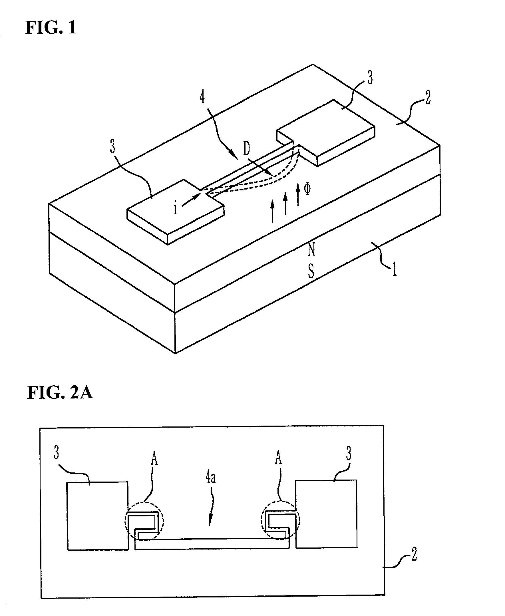
[0025]Referring now to FIG. 1, the electromagnetic-type micro-electromechanical actuator includes a magnetic substance 1, a micro electronic substrate 2 formed on the substrate 1, and electrodes 3 formed on both sides of the micro electronic substrate 2. Further, a conductive beam 4 is formed so that the electrodes 3 on both sides can be supported.

[0026]At this case, the magnetic substance 1 may be formed of a magnet such as paramagnetic substance or may be formed by coils wound on the micro electronic substrate 2. The micro electronic substrate 2 may be formed of one of silicon, glass, PCB (printed circuit board), acryl, polymer, metal and a...


PUM


Abstract

The present invention relates to a micro-electromechanical actuator. An electromagnetic-type micro-electromechanical actuator of the present invention has a conductive beam formed in a micro electronic substrate on an upper side of a magnetic substance, so that the conductive beam can be moved toward an in-plane mode in parallel to the micro electronic substrate depending on a direction that current flows. Therefore, the micro-electromechanical actuator can be applied to most of electromagnetic micro-electromechanical systems that require an in-plane mode.

Description

BACKGROUND OF THE INVENTION[0001]1. Field of the Invention[0002]The invention relates generally to an actuator to be used in a micro-electromechanical system, and more particularly to, an electromagnetic-type actuator for providing a parallel displacement to the surface of a microelectronic substrate.[0003]2. Description of the Prior Art[0004]An actuator which is the most important component in the micro-electromechanical system, has been implemented through a lot of driving principles. As one example, there are an electrostatic actuator using an electrostatic force between two different electrodes, a piezoelectric actuator using a piezoelectric material, a thermal actuator using thermal expansion of materials or thermal expansion of air contained within a limited space, an electromagnetic actuator using an electromagnetic force, and the like.[0005]Many micro-electromechanical devices have been manufactured by means of above-mentioned driving principles. For example, there are a mic...

Claims


Application Information

Patent Timeline
IPC IPC(8): H01H51/22H02K33/10B81B3/00G02B6/26G02B6/35H01H1/00H01H53/06
CPCB81B3/0021G02B6/3572H01H1/0036H01H53/06B81B2201/038B81B2203/0109B81B2203/051B81B2203/056H01H2001/0078G02B6/266G02B6/3546B81B2203/058H02K33/10
Inventor KO, JONG SOOLEE, DAE SIKLEE, MYUNG LAEJUN, CHI HOONKIM, YOUN TAE
Owner ELECTRONICS & TELECOMM RES INST
Why Eureka
Try Eureka