Methods and apparatus for analyzing mirror reflectance

a mirror reflectance and apparatus technology, applied in the direction of optical radiation measurement, reflective surface testing, instruments, etc., can solve the problems of reducing the calibration accuracy of the remote sensing instrument's output measurement, affecting the quality of the scan mirror reflectance, and affecting the calibration accuracy of the remote sensing instrument, so as to accurately and accurately assess the reflectance characteristics, accurately determine the quality of the mirror reflectance value, and accurately adjust the signal measurement

Active Publication Date: 2006-01-17
HARRIS CORP
View PDF15 Cites 6 Cited by
  • Summary
  • Abstract
  • Description
  • Claims
  • Application Information

AI Technical Summary

Benefits of technology

[0015]Another object of the invention is to reduce the number of manual measurements required to ascertain the reflectivity of a mirror at different angles of incidence left unmeasured across a broad spectrum of wavelengths.
[0017]A further object of the invention is to quickly determine the quality of mirror reflectance values and to identify, assess, and estimate errors and resultant calibration uncertainties associated with variation of mirror reflectance values at different angles of incidence.
[0018]A still further object of the invention is provide reflectance values over a broad range of wavelengths and at different angles of incidence to support accurate correction of signal measurements received via a scanning mirror.
[0019]It is yet a further object of the invention to efficiently and accurately assess reflectance characteristics for scanning mirrors within a controlled laboratory environment as well as for scanning mirrors integrated within remote sensing equipment.
[0023]The approach uses equations based on the Fresnel equations (but not directly derived) for reflectance in which reflectance is calculated as a function of the angle of incidence of incoming light to the scanned mirror used to collect the signal. The angle of incidence-based approach allows accurate relative reflectance values to be calculated over a broad range of wavelengths and angles of incidence without detailed knowledge of the optical properties of the coating material and the substrate underneath.
[0025]By repeating the methods and techniques described for a set of reference angles of incidence across a set of reference wavelengths, accurate reflectance calculations can be made that provide complete coverage of a desired range of angles of incidence, for an identified spectrum. The methods and techniques described are particularly useful for calibrating measurements made with remote sensing instruments that use scanned mirrors because more accurate corrections can be made while the need for physical measurements is minimized.

Problems solved by technology

While this approach is simple in concept, a significant complication is that the reflectance of a scanning mirror varies, depending upon the angle at which light strikes the mirror (i.e., the “angle of incidence” of the incoming light).
A further complication is that the reflectance of the S-polarization and P-polarization components of light at a particular wavelength vary differently as the angle of incidence changes.
Unless corrections are made to account for the changes in a scanning mirror's S-polarization reflectance and P-polarization reflectance as a function of the angle of incidence, the uncorrected changes will decrease the calibration accuracy of the remote sensing instrument's output measurements.
For most remote sensing mirrors, calibration uncertainties associated with scan mirror reflectance are made more serious by the use of absorbing coatings on the mirror surfaces to protect them from damage.
The difficulty for instrument manufacturers is that the over-coating prescription is not necessarily known (e.g., proprietary coatings are used) or the manufacturing and storage process may not be controlled well enough to allow accurate calculation of the reflectance from basic optical constants of the deposited protective material.
Furthermore, the optical qualities of over-coatings can change over time, due to prolonged exposure to extreme conditions, requiring that the reflectivity of a mirror be periodically reassessed for recalibration purposes.
However, as previously discussed, this approach is typically hindered by a lack of information with respect to proprietary mirror coatings, and / or changes in optical characteristics due to environmental effects.
Although such polynomial equations are able to fit measured reflectance values to a rather high degree of precision, a polynomial equation is not based upon a mathematical model of the physical phenomenon of mirror reflectance.
Therefore, a polynomial equation does not fundamentally provide a true representation of the expected behavior of the mirror as a function of angle of incidence.
Another deficiency associated with the use of polynomial equations to model mirror reflectance is that the approach requires a significant number of manual measurements of mirror reflectance versus angle of incidence so that an accurate polynomial equation can be developed that matches the resulting measured reflectance values.
Such measurements must be taken for each wavelength with which the mirror will be used, because previously developed polynomial equations are not based upon a physical model and, therefore, cannot be accurately relied upon to predict reflectivity of the mirror at other wavelengths.
Although simple in concept, such an approach requires a large number of measured reflectance value data points and sufficient storage capacity to support use of the technique.
While all three approaches can be used to extrapolate the reflectance values of a coated mirror in a laboratory (i.e., with the assistance of special test equipment and special test configurations), all three approaches suffer from serious deficiencies with respect to their ability to be adapted for use in deployed devices (i.e., outside of a controlled laboratory environment in which specialized support equipment and personnel are not readily available).
Furthermore, these approaches cannot be used to develop high confidence reflectance values at multiple angles of incidence based upon reflectance values measured at one or a few angles of incidence, thereby significantly increasing the number of measured reflectance values required to facilitate generation of accurate reflectance values across multiple angles of incidence.
Such devices are, typically, constrained in size, weight and design and are inaccessible to technicians with the required calibration equipment.

Method used


Image

  • Methods and apparatus for analyzing mirror reflectance
  • Methods and apparatus for analyzing mirror reflectance
  • Methods and apparatus for analyzing mirror reflectance

Examples


Embodiment Construction

[0039]Preferred embodiments according to the present invention are described below with reference to the above drawings, in which like reference numerals designate like components.

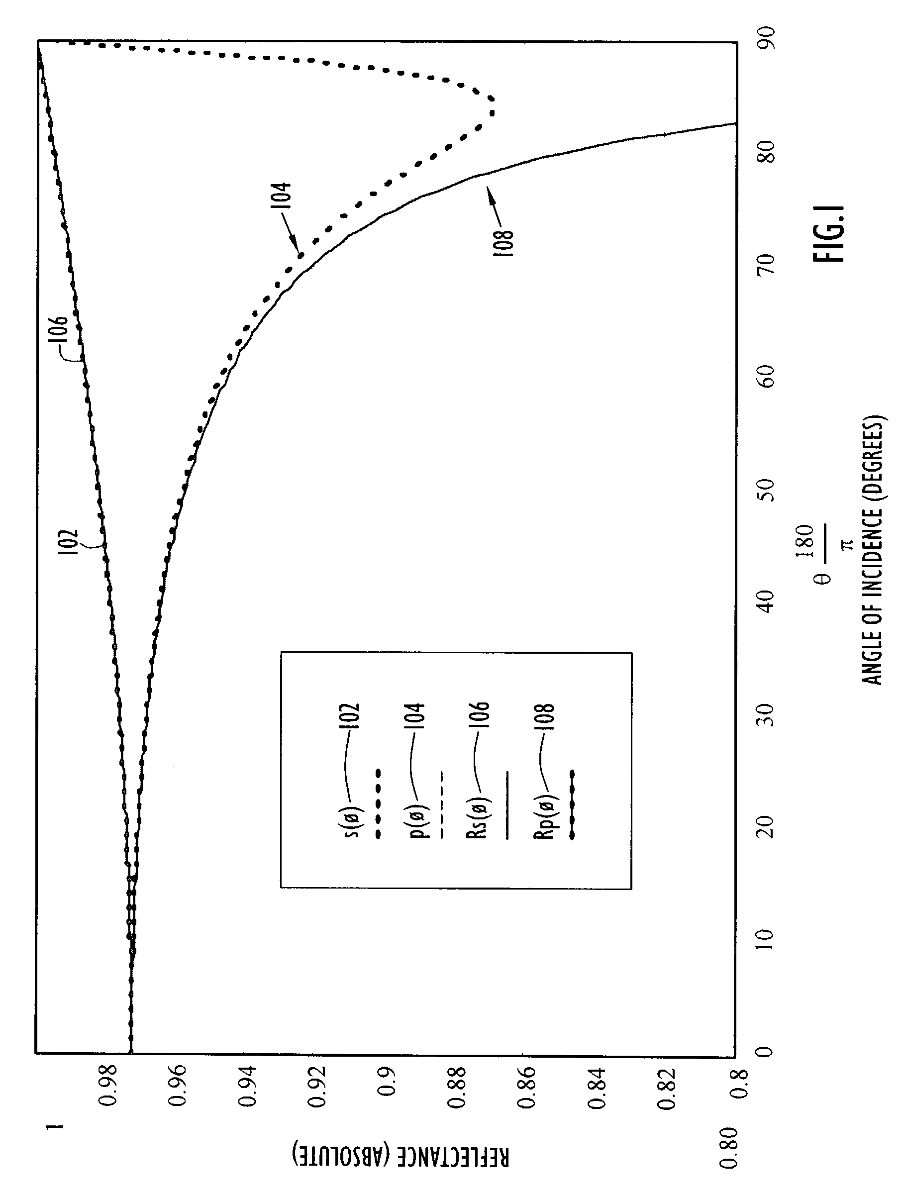
[0040]The Fresnel reflection from smooth metal surfaces is a well-understood and highly characterized phenomenon. Light at a single wavelength can be characterized by an S-polarization vector and a P-polarization vector. The S-polarization electric vector is always parallel to the mirror surface (by definition in the measurement setup context), resulting in very little effect of angle of incidence on that polarization. However, the P-polarization vector can be significantly affected by angle of incidence. Approximate Fresnel reflectance equations for S-polarization and P-polarization as a function of angle from a smooth metal surface are given by: RP=(n2+k2)⁢cos2⁢θ-2⁢⁢n⁢⁢cos⁢⁢θ+1(n2+k2)⁢cos2⁢θ+2⁢⁢n⁢⁢cos⁢⁢θ+1(1)and,RS=(n2+k2)-2⁢⁢n⁢⁢cos2⁢θ+⁢cos2⁢⁢θ(n2+k2)+2⁢⁢n⁢⁢cos2⁢θ⁢+cos2⁢⁢θ(2)

[0041]The index of refraction...


PUM


Abstract

Methods and apparatus are described for assessing the reflective properties of mirrors at different angles of incidence without precise knowledge of the mirror's basic optical constants and / or without precise knowledge of the mirror's over-coating prescription. Reflectance values can be accurately calculated for multiple angles of incidence based upon measurement data collected for a single angle of incidence. The approach uses equations based on the Fresnel equations for reflectance in which reflectance is calculated as a function of the angle of incidence of incoming light to the scanned mirror used to collect the signal. The angle of incidence-based approach allows accurate reflectance values to be calculated over a broad range of wavelengths and angle of incidences without detailed knowledge of the optical properties of the coating material and the substrate underneath. The described methods and apparatus are particularly useful for calibrating measurements made with remote sensing instruments that use scanned mirrors.

Description

BACKGROUND OF THE INVENTION[0001]1. Field of the Invention[0002]The invention relates to methods and apparatus for assessing the reflective properties of mirrors at different angles of incidence without precise knowledge of the mirror's basic optical constants and / or without precise knowledge of the mirror's over-coating prescription. More particularly, the invention relates to accurately estimating reflectance values for multiple angles of incidence based upon measured reflectance values collected for a single or a few angles of incidence.[0003]2. Description of the Related Art[0004]Many remote sensing instruments make use of mirrors that scan over a wide range of angles to produce a large field-of-view image, such as those images typically taken by satellites of the earth, or images taken by optical telescopes of distant planets and galaxies. While this approach is simple in concept, a significant complication is that the reflectance of a scanning mirror varies, depending upon the...

Claims


Application Information

Patent Timeline
Patent Type & Authority Patents(United States)
IPC IPC(8): G01J4/00
CPCG01M11/005G01N21/55G01N21/21
Inventor SMITH, DAVID S.
Owner HARRIS CORP
Why Eureka
Try Eureka