
Methods, apparatus and computer program products that perform layout versus schematic comparison of integrated circuits using advanced pin coloring operations

a technology of integrated circuits and pin coloring, applied in the field of apparatus and methods for verifying microelectronic circuits and systems, can solve the problems of ambiguity in selecting matching nodes, computational intractable problems, and performance of these operations

Inactive Publication Date: 2006-01-17
SYNOPSYS INC
View PDF24 Cites 29 Cited by
  • Summary
  • Abstract
  • Description
  • Claims
  • Application Information

AI Technical Summary

Benefits of technology

[0015]It is therefore an object of the present invention to provide improved methods, apparatus and computer program products that can perform post-layout verification of microelectronic integrated circuits.
[0016]It is also an object of the present invention to provide improved methods, apparatus and computer program products that can perform layout versus schematic comparison of integrated circuits.
[0017]It is another object of the present invention to provide methods, apparatus and computer program products that can perform layout versus schematic comparison of hierarchical integrated circuits having symmetrical cells therein.

Problems solved by technology

One difficulty associated with the performance of these operations may be caused by a dissimilarity in the labeling of nets and devices in the extracted layout netlist relative to the electrical schematic netlist.
The unambiguous determination of isomorphism between two arbitrary graphs may be a computationally intractable problem.
Unfortunately, some circuits may exhibit symmetry that may cause different nodes to receive the same color because the “neighborhoods” associated with these nodes are similar.
When two or more nodes have the same color, ambiguities in selecting matching nodes may arise.
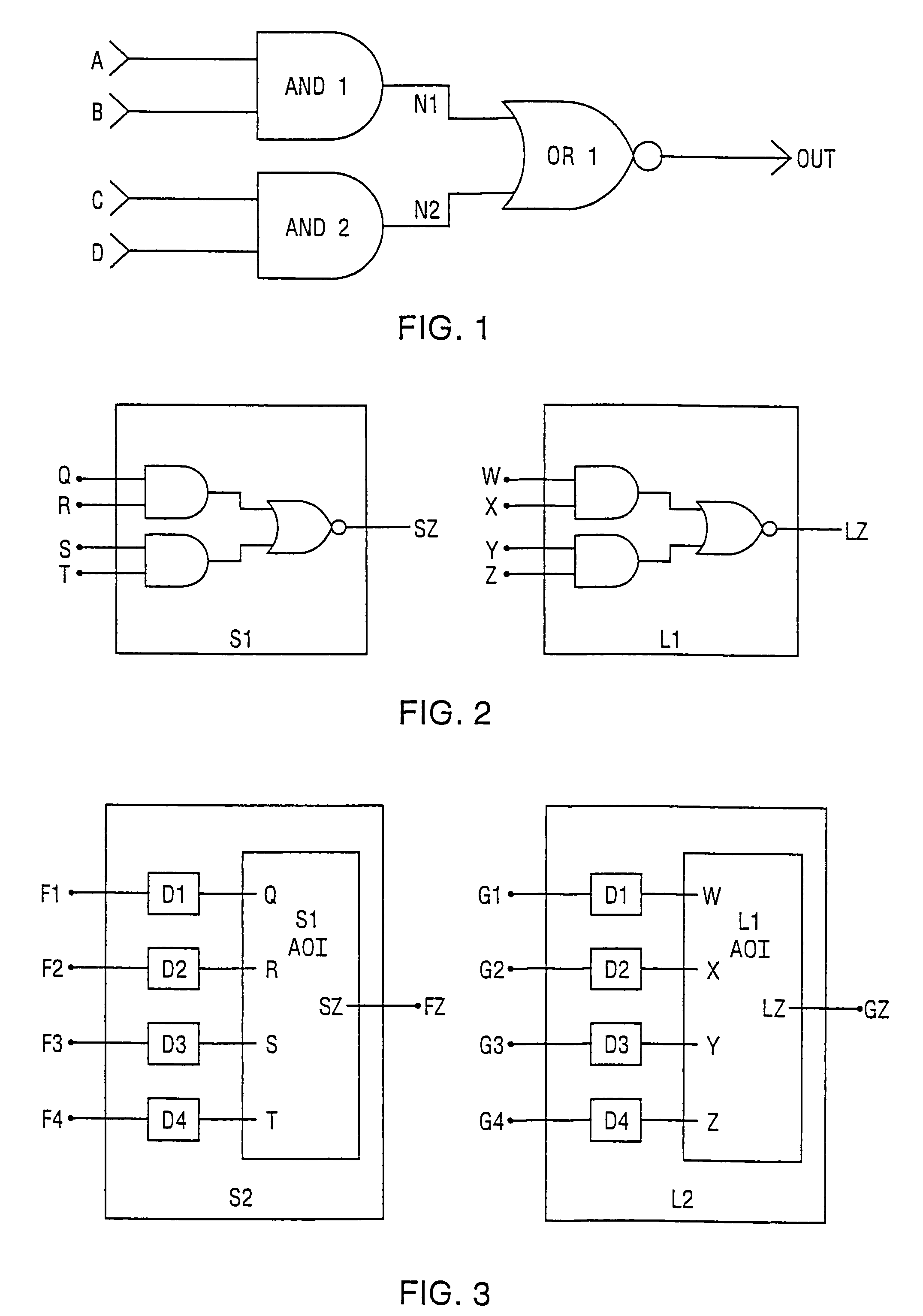
However, because the symmetry of the design may cause the ports of each AOI child cell in FIG. 2 to acquire the same color when the schematic and layout graphs of the AOI child cells have been colored to an equilibrium state, a conventional LVS tool may make an arbitrary mapping which may be incorrect (e.g., Q→W, R→Y, S→X, T→Z).
Thus, LVS software may report a mismatch between an original electrical schematic netlist and an extracted layout netlist, even though it is possible to make assignments among symmetric nodes that will result in a match.
Typically, a consequence of this limitation in LVS software is that the software user must manually intervene by providing the LVS software with specific assignments to resolve ambiguities due to symmetry.
Since it is not always clear where an erroneous guess was made, such manual intervention may be time consuming.
For large and highly symmetric designs such as memories and gate arrays, these limitations may significantly reduce the utility of conventional LVS tools including hierarchical LVS tools using general-purpose graph isomorphism algorithms.
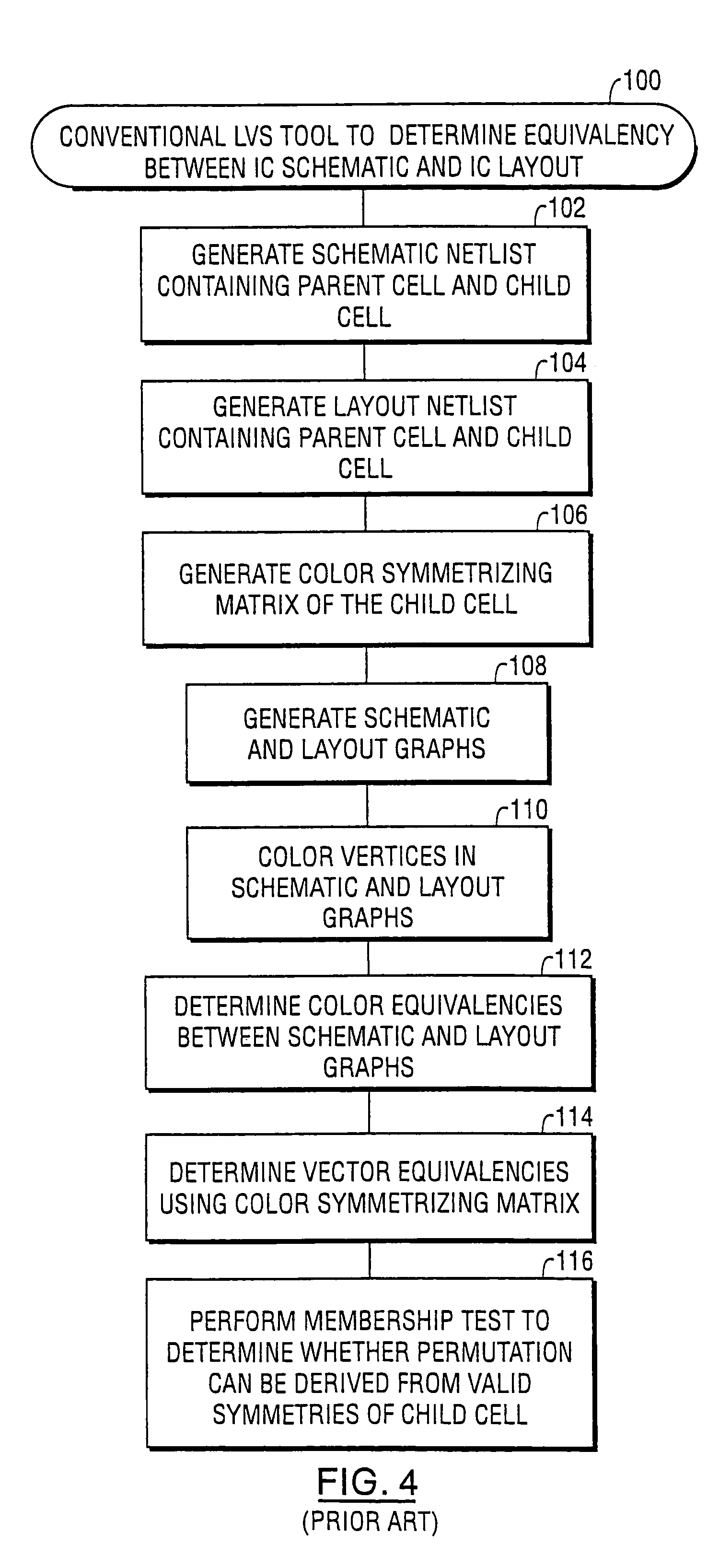
Unfortunately, although the software tool of FIG. 4 typically requires no human intervention and works well with most designs exhibiting symmetry, the automatic performance of membership test to validate the accuracy of the matched layout and schematic may incur an unduly large computational expense and limit the applicability of the above software to large integrated circuit designs having large degrees of symmetry.
This is because the penalty for erroneously identifying equivalent circuits as nonequivalent (i.e., manual intervention by the user) is far less onerous than the penalty for misidentifying non-equivalent circuits as equivalent (i.e., the expense of prototyping and manufacturing an incorrect design).

Method used


Image

  • Methods, apparatus and computer program products that perform layout versus schematic comparison of integrated circuits using advanced pin coloring operations
  • Methods, apparatus and computer program products that perform layout versus schematic comparison of integrated circuits using advanced pin coloring operations
  • Methods, apparatus and computer program products that perform layout versus schematic comparison of integrated circuits using advanced pin coloring operations

Examples


first embodiment

[0087]Referring now to FIGS. 20–21, preferred operations performed by embodiments of a layout versus schematic (LVS) comparison tool 430A according to the present invention will be described. These operations include coloring a graph of an integrated circuit to an equilibrium state and then identifying a “provisional” swap group of nodes having the same color within the colored graph, Blocks 430A1, 430A2. The colored graph may be a colored layout graph or a colored schematic graph of the integrated circuit. For example, as illustrated by FIG. 21, the colored graph may be a colored bipartite graph having both net and device nodes therein. This “provisional” swap group of nodes corresponds to pins of a device that may be swappable by virtue of the fact that the nodes associated with the pins have the same color after a graph coloring operation has been performed. A new (e.g., unique) color is then assigned to a node within the identified swap group, Block 430A3. An operation is then p...

second embodiment

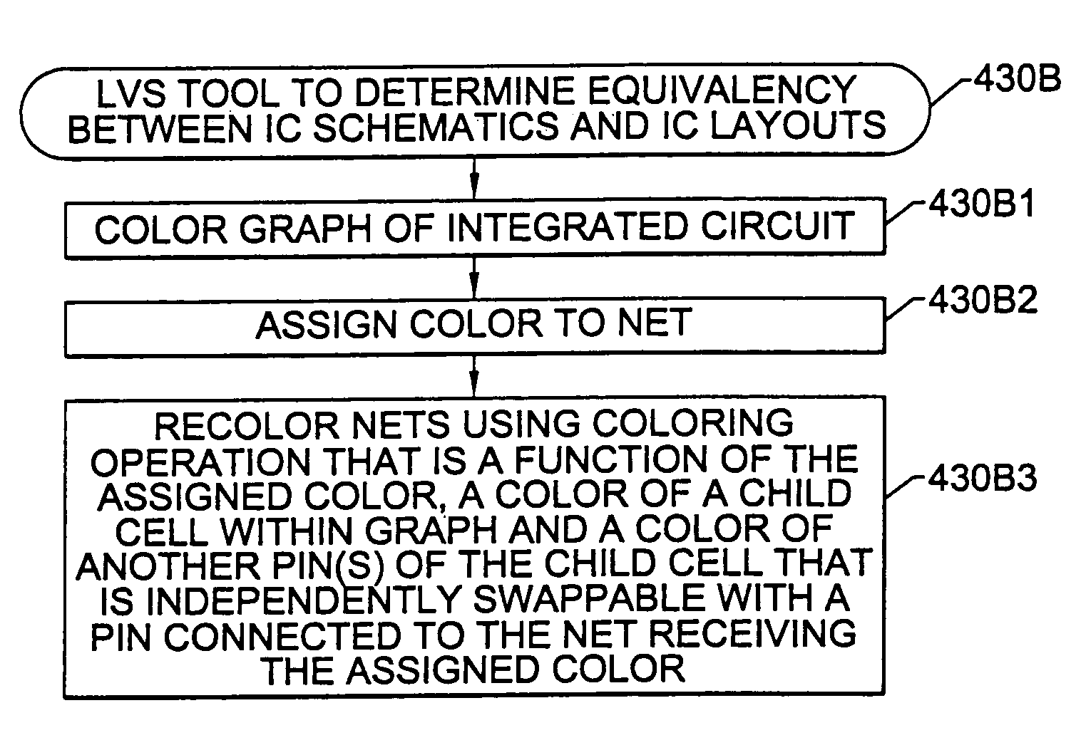
[0093]Referring now to FIGS. 22–26, preferred operations performed by a layout versus schematic (LVS) comparison tool 430B according to the present invention will be described. These operations include coloring a schematic graph of a parent cell to obtain a first set of net colors for a first plurality of nets in the schematic graph, Block 430B1. Next, a new color is assigned to a first net in the first plurality of nets, Block 430B2. This first net is connected to a first pin of a child cell within the parent cell. The new assigned color is preferably unique to the other colors in the first set. A net recoloring operation is then performed, Block 430B3. This net recoloring operation preferably includes recoloring the first set of net colors by determining a new color for the first net using a coloring operation that is a function of the assigned color, a color of the child cell (i.e., device value of the child cell) and a color of each of the first plurality of nets that are electr...


PUM


Abstract

A layout versus schematic (LVS) comparison tool determines one-to-one equivalency between an integrated circuit schematic and an integrated circuit layout by performing operations to color a schematic graph of a parent cell to an equilibrium state. An operation is then performed to recolor nets connected to first and second child cells having the same device value within the parent cell, using a net coloring operation that recolors a first plurality of symmetric pins of the first child cell and recolors a second plurality of symmetric pins of the second child cell. Distinct device values are then generated for the first and second child cells by determining a first product of the colors of the recolored first plurality of symmetric pins and a second product of the colors of the recolored second plurality of symmetric pins. The operations to recolor the nets preferably include coloring a first pin of a child cell within a parent cell using a pin coloring operation that is a function of a device value of the child cell and a color of each of the pins of the child cell that are independently swappable with the first pin, but is independent of a color of a second pin of the child cell that is dependently swappable with the first pin.

Description

CROSS-REFERENCE TO PRIORITY APPLICATION[0001]This application is a divisional of U.S. application Ser. No. 10 / 279,337, filed Oct. 24, 2002, now U.S. Pat. No. 6,799,307, which is a divisional of U.S. application Ser. No. 09 / 505,499, filed Feb. 17, 2000, now U.S. Pat. No. 6,499,130, the disclosures of which are hereby incorporated herein by reference.FIELD OF THE INVENTION[0002]This invention relates to the design, layout, testing and manufacture of microelectronic circuits and systems, and more particularly to apparatus and methods for verifying microelectronic circuits and systems prior to manufacture.BACKGROUND OF THE INVENTION[0003]Present day ultra-large-scale integration (ULSI) circuits may include hundreds of thousands or millions of interconnected active electronic devices on an integrated circuit chip. The large capital investment required to fabricate and test large scale integrated circuits prior to sale to a customer and the difficulty, expense and loss of goodwill associa...

Claims


Application Information

Patent Timeline
IPC IPC(8): G06F17/50
CPCG06F17/5072G06F30/392
Inventor LIPTON, GARY BRUCEJOHNSON, IV, HARRY CLARKSONWHITE, JONATHAN CALVIN
Owner SYNOPSYS INC
Learn More