Outlets for a pyrolytic waste treatment system

a waste treatment system and pyrolysis technology, applied in the direction of lighting and heating apparatus, combustion types, energy input, etc., can solve the problems of pyrolysis using waste materials, turbulence in the burning chamber, and the conversion is far less compl

Inactive Publication Date: 2006-01-24
APS IP HLDG
View PDF7 Cites 45 Cited by
  • Summary
  • Abstract
  • Description
  • Claims
  • Application Information

AI Technical Summary

Benefits of technology

[0004]In contrast, the pyrolytic process employs high temperature in, most desirably, an atmosphere substantially free of oxygen (for example, in a practical vacuum), to convert the solid components of waste to a mixture of solids, liquids, and gases with proportions determined by operating temperature, pressure, oxygen content, and other conditions. The solid residue remaining after pyrolysis commonly is referred to as char. The vaporized product of pyrolysis is often further treated by a process promoting oxidation, which “cleans” the vapors to eliminate oils and other particulate matter there from, allowing the resultant gases then to be safely released to the atmosphere.

Problems solved by technology

Unlike incineration, pyrolysis is the destructive decomposition of waste materials using indirect heat in the absence of oxygen.
Burning wastes through incineration with direct flame in the presence of oxygen can be explosive, causing turbulence in the burning chamber, which fosters a recombination of released gases.
Waste destruction in an oxygen-rich atmosphere makes conversion far less complete, is highly inefficient and creates harmful substances.

Method used


Image

  • Outlets for a pyrolytic waste treatment system
  • Outlets for a pyrolytic waste treatment system

Examples


Embodiment Construction

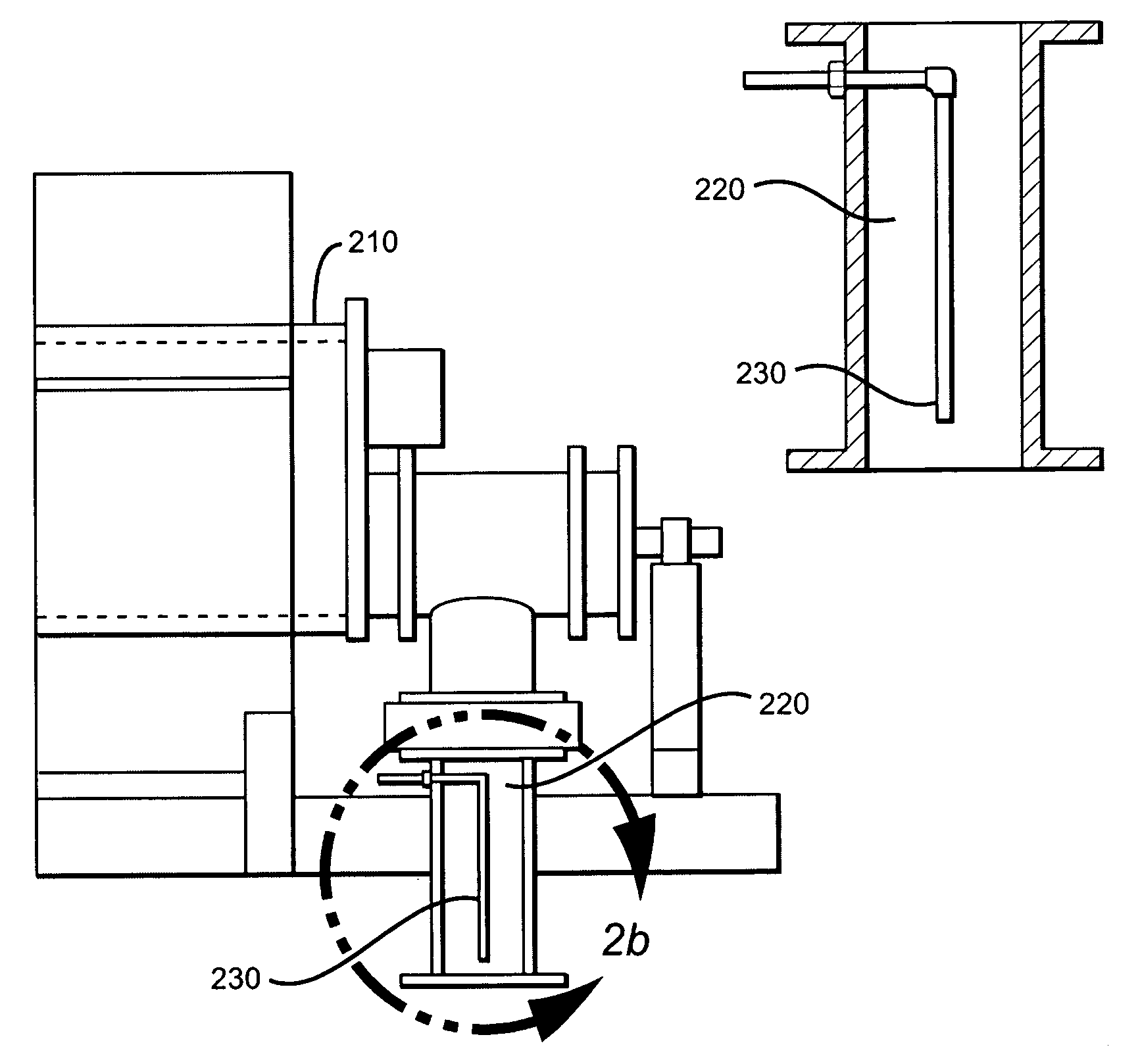
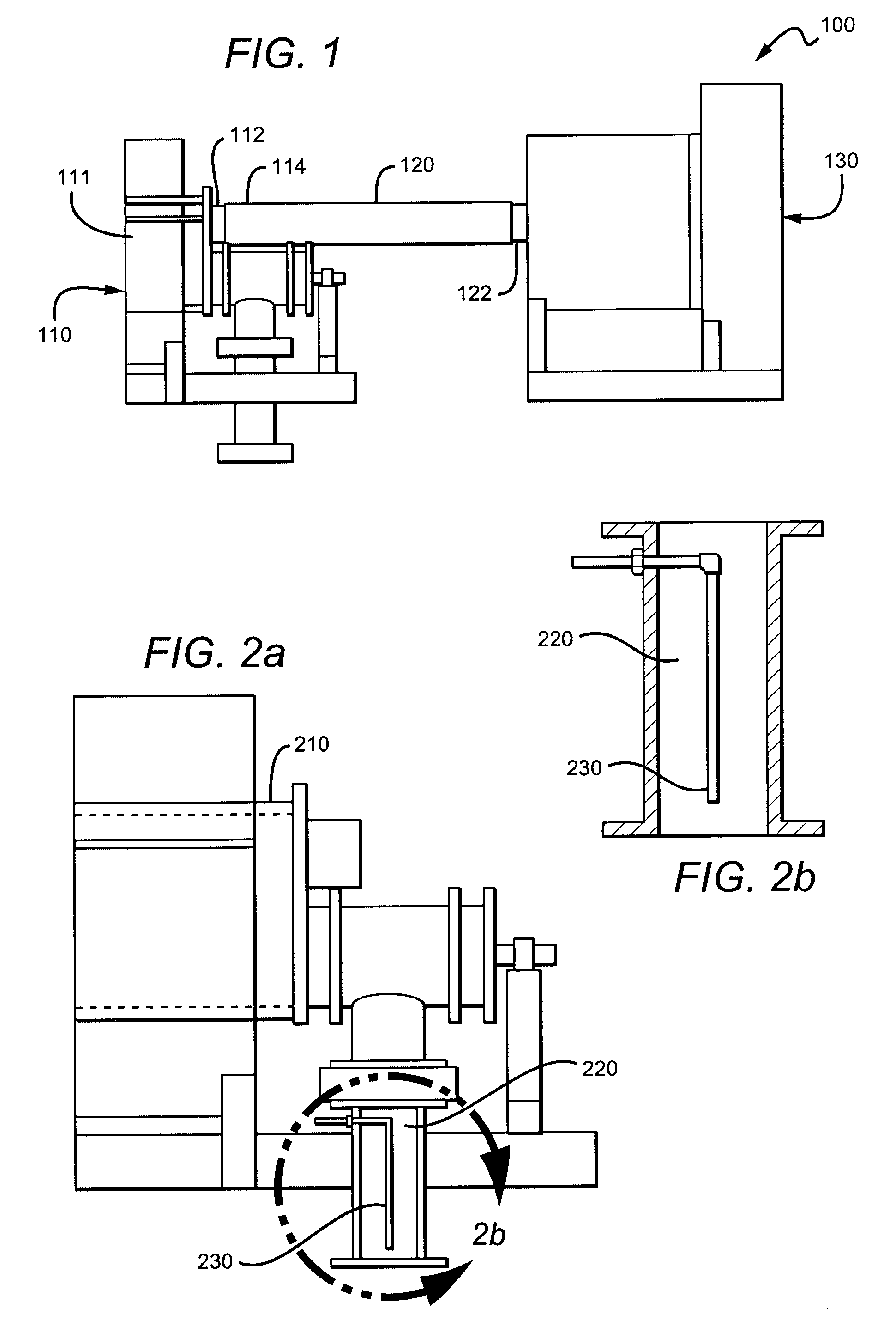
[0012]In FIG. 1, a pyrolytic system 100 generally comprises a pyrolytic converter 110 coupled to a thermal oxidizer 130 by an outlet 120.

[0013]Pyrolysis of waste produces gases the composition of which depends on the composition of the waste being treated. However, many of the gases produced have a tendency to form a solid residue as they cool. As such, outlets have a tendency to clog. Clogging of gas outlet lines can be prevented or minimized at least by preventing gasses from cooling in the lines, causing gasses to move more quickly through the lines, and dislodging any residue as it forms. One way to implement all three of these options is by injecting steam into gas outlet lines in a manner that helps move gas through the lines and helps dislodge any residue that forms.

[0014]Outlet 120 has gases enter it via vapor residue outlet 112. The system further comprises a steam injection port 114 used to inject high pressure steam into outlet 120.

[0015]Port 122 is preferably coupled to ...


PUM

PropertyMeasurementUnit
temperatureaaaaaaaaaa
pressureaaaaaaaaaa

Abstract

The inventive subject matter is directed toward a pyrolytic waste treatment system comprising an outlet adapted to channel a composition out of a pyrolysis chamber. A mechanism is used for cleaning the outlet during operation of the pyrolytic system.

Description

[0001]This application claims the benefit of U.S. provisional application No. 60 / 497,397 filed on 21 Aug. 2003 incorporated herein by reference in its entiretyFIELD OF THE INVENTION[0002]The field of the invention is pyrolytic waste treatment.BACKGROUND OF THE INVENTION[0003]Pyrolysis is a known method for treatment of waste. Examples of pyrolytic waste treatment systems can be found in U.S. Pat. Nos. 4,759,300, 5,653,183, 5,868,085, and 6,619,214. Unlike incineration, pyrolysis is the destructive decomposition of waste materials using indirect heat in the absence of oxygen. Burning wastes through incineration with direct flame in the presence of oxygen can be explosive, causing turbulence in the burning chamber, which fosters a recombination of released gases. Waste destruction in an oxygen-rich atmosphere makes conversion far less complete, is highly inefficient and creates harmful substances.[0004]In contrast, the pyrolytic process employs high temperature in, most desirably, an ...

Claims


Application Information

Patent Timeline
Patent Type & Authority Patents(United States)
IPC IPC(8): F23L17/16F23J1/02F23J1/00C10BF23GF23G5/12F23G7/04F23K3/00F23M5/02
CPCC10B47/28C10B47/44C10B53/00F23G5/0273F23G5/46F23G5/16Y02E20/12F23G2201/303F23G2206/10Y02P20/129F23G7/04F23M5/02F23G5/12
Inventor COLE, CAMERONDE LA TORES, RAULCOLE, TOBY L.WATTS, DAN
Owner APS IP HLDG
Why Eureka
Try Eureka