Multiple source collimated beam luminaire

a collimated beam and light source technology, applied in the direction of lighting applications, light source combinations, ways, etc., can solve the problems of high cost, large volume, unsuitable for mass production, etc., and achieve the effect of simple operation and electrical efficiency

Inactive Publication Date: 2006-01-24
FARLIGHT
View PDF12 Cites 59 Cited by
  • Summary
  • Abstract
  • Description
  • Claims
  • Application Information

AI Technical Summary

Benefits of technology

[0004]It is therefore a principal object of the present invention to provide a luminaire which produces a single collimated beam

Problems solved by technology

Unfortunately, these devices are expensive, bulky, cumbersome, require fin

Method used


Image

  • Multiple source collimated beam luminaire
  • Multiple source collimated beam luminaire
  • Multiple source collimated beam luminaire

Examples


first embodiment

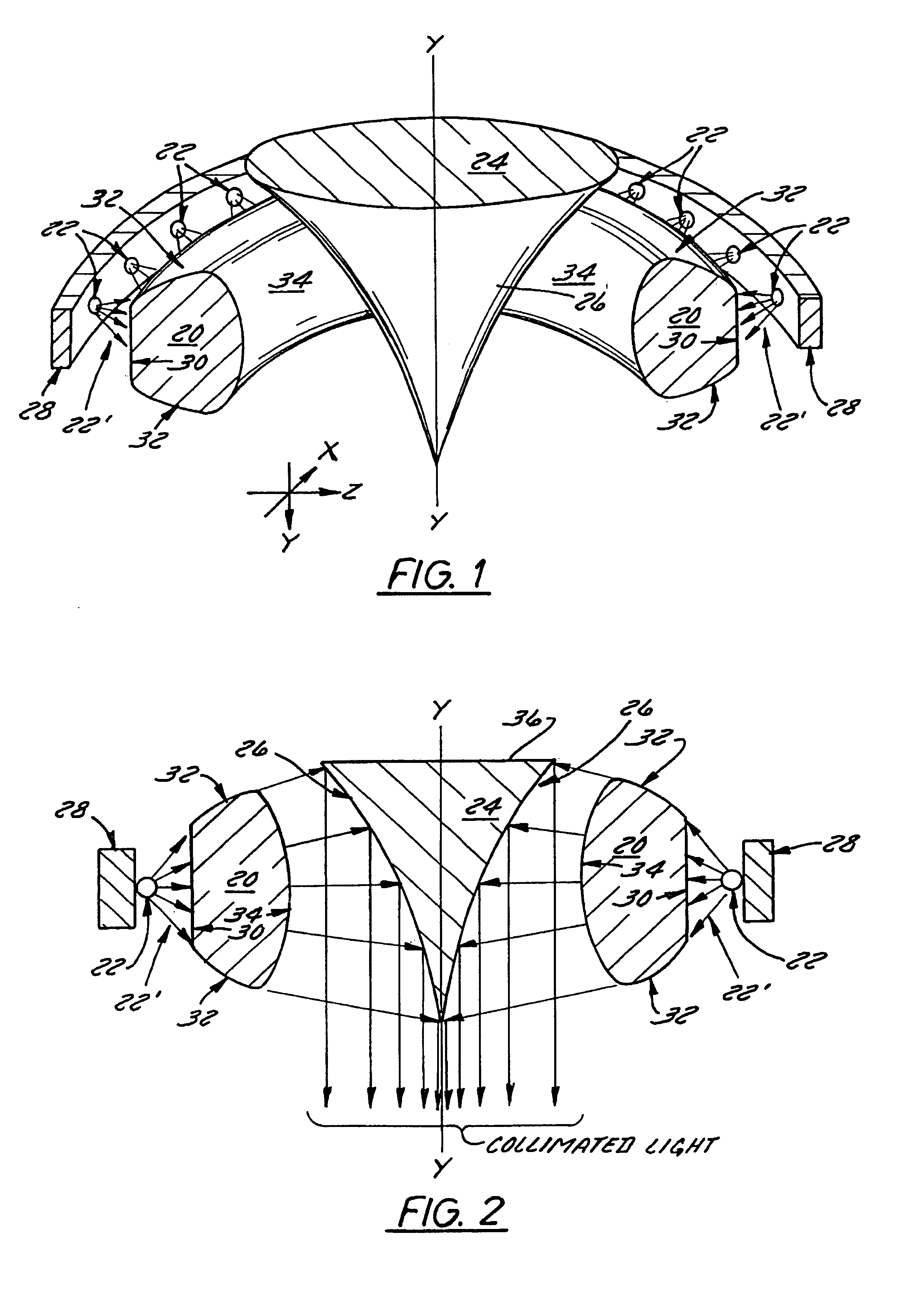
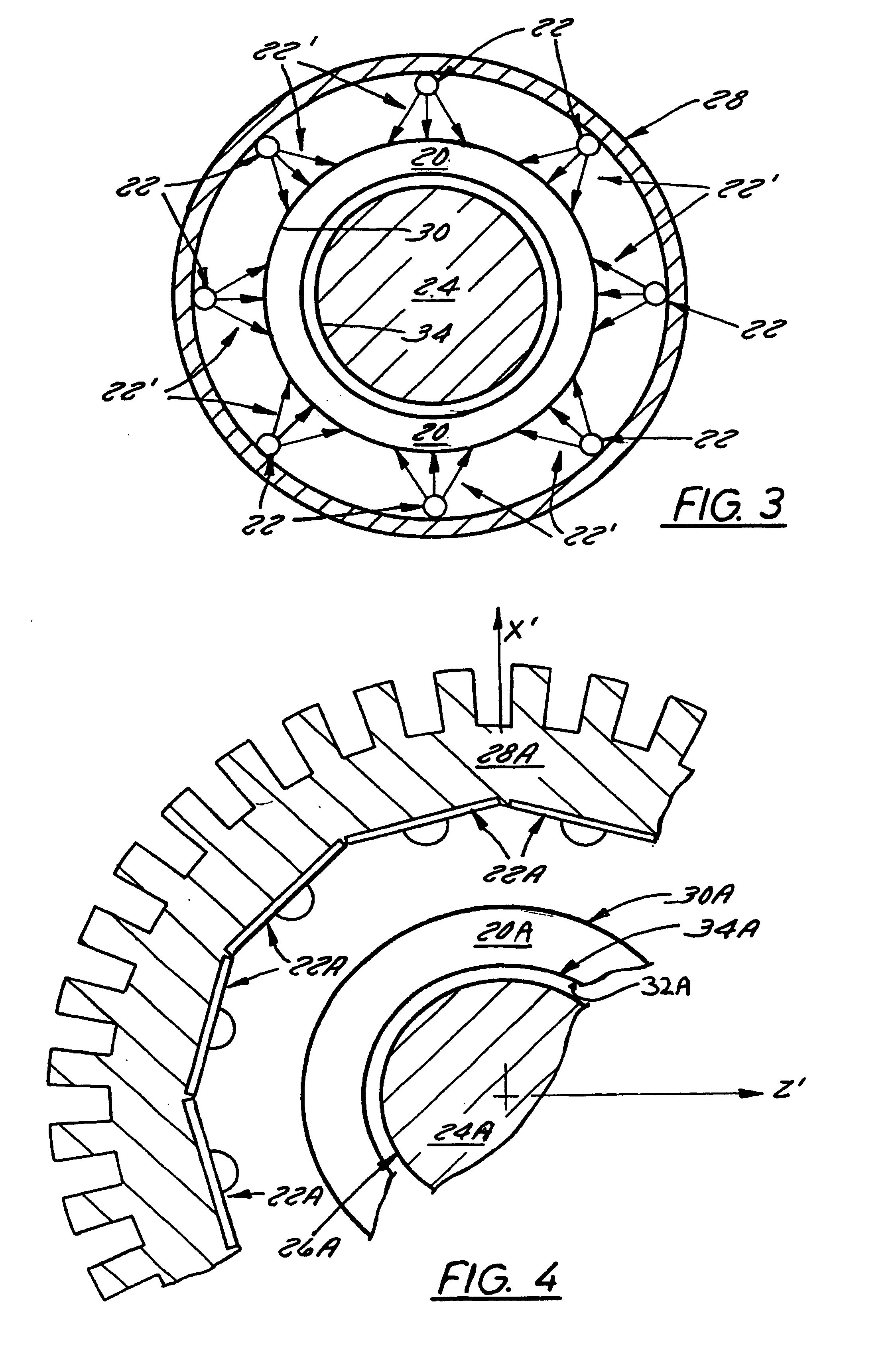
[0040]It is well known that, in general, LEDs emit a highly divergent beam. The quasi-toroidal light transforming collector 20A is therefore designed to compensate for this divergency and to transform light output from the LEDs into a more usable spatial distribution prior to being reflected by curved conical collimating combiner 24A. Further in this regard, FIG. 4A shows another embodiment of the present invention in which the quasi-toroidal light transforming collector 20A comprises a number of concentric quasi-toroidal components 201, 202 and 203 fabricated from material with different indices of refraction. Each component in this embodiment is disposed close to the axis Y′—Y′ and has an index of refraction higher than the adjacent one. Specifically, external component 201 has the lowest index of refraction and internal component 203 has the highest index of refraction of these components. Those skilled in the art of optics will understand that each component will operate as a cy...

second embodiment

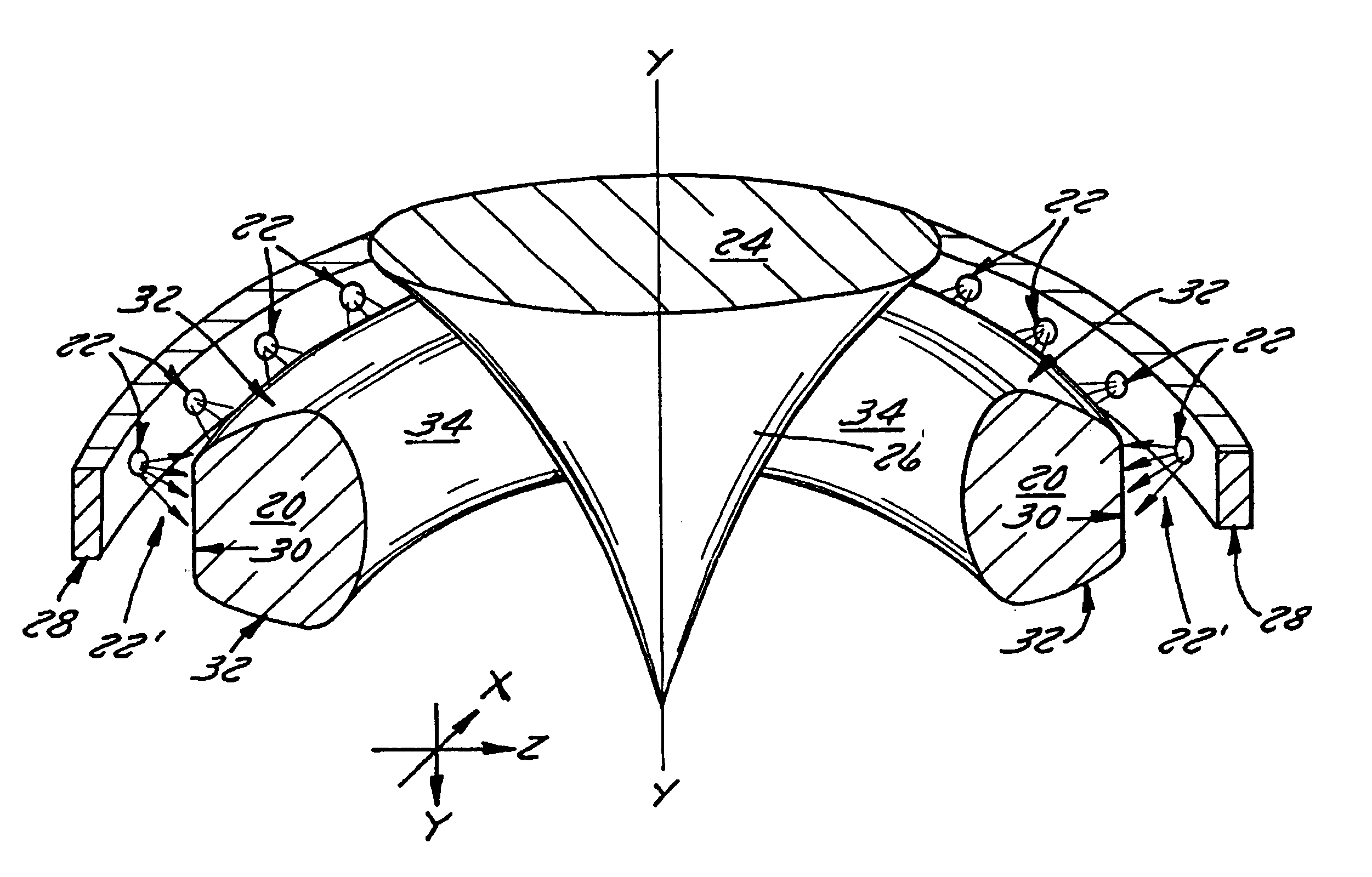
[0041]It is also known, that in general LEDs generate heat. Further in that regard, LED performance and longevity is thus dependent upon the removal of such LED-generated heat and therefore, the luminaire of the second embodiment preferably includes an effective amount of heat-transfer surface area. In this regard, the light source support structure 28A (FIG. 4) may be made of a suitable durable heat-transmissive material such as stainless steel or aluminum, which has sufficient mass and surface area to provide satisfactory “heat-sink” properties, as may be desired.

[0042]Next referring to FIG. 5, another embodiment of the present invention is shown to comprise a quasi-toroidal light transforming collector 20B, a curved conical collimating combiner 24B, a light source support structure 28B, and a plurality of light sources 22B, each light source comprising a combination of red, green, and blue light emitting diodes connected to an R, G, B-controlled power supply. As is seen, there ar...


PUM


Abstract

A luminaire comprising a light transmissive optical element, a plurality of light sources, a light source support structure, and a light reflective surface. The light transmissive optical element, which preferably is a quasi-toroidal light transforming collector, is spaced from and disposed about an axis. The plural light sources are disposed radially outwardly of the optical element relative to the axis, to produce a corresponding plurality of light beams. Each light source directs its light beam toward the optical element. The optical element is shaped and adapted to collect and transform the light beams and pass them in the direction of the axis. The light reflective surface, which preferably is a curved conical collimating combiner, is spaced from the optical element, and is disposed along the axis. The light reflective surface is optically shaped to redirect along the axis and combine the plurality of light beams passed by the optical element to produce a collimated beam of light from the re-directed plurality of light beams.

Description

TECHNICAL FIELD[0001]The present invention, in general, is directed to a multiple source lighting device. The invention, more particularly, is directed to a luminaire that produces a collimated beam of light from a plurality of sources spaced about the collimator.BACKGROUND OF THE INVENTION[0002]It is well known that in many practical applications it is desirable to combine light from multiple light sources into one single beam. Of special interest is application of semiconductor-based light sources, such as laser diodes and light emitting diodes (LEDs). Even with recent progress in semiconductor technologies and advances toward more powerful LED designs, many applications still require the combined light output from a plurality of sources to achieve desirable luminous flux and / or color combinations. The dominant state-of-the-art solution is based on the use of an array of multiple individual peripheral optical elements described, for example, in U.S. Pat. Nos. 5,369,659 and 5,592,5...

Claims


Application Information

Patent Timeline
IPC IPC(8): F21V9/06F21S8/00F21V5/00F21V5/04F21V13/04F21V29/00
CPCF21V5/00F21V5/04F21V13/04F21V29/004F21V29/77F21W2111/02F21Y2101/02F21Y2103/022F21Y2113/005F21W2111/00F21Y2115/10F21Y2103/33F21Y2113/13F21V29/89F21V5/043
Inventor RIZKIN, ALEXANDERAGUROK, IL'YATUDHOPE, ROBERT H.
Owner FARLIGHT
Why Eureka
Try Eureka