Energy efficient lighting apparatus and use thereof

a lighting apparatus and energy-saving technology, applied in the field of energy-saving lighting apparatus, can solve the problems of inconvenient use, inconvenient maintenance, and inability to meet the needs of lighting and heating equipment, and achieve the effects of improving energy-efficiency, maximizing energy-efficiency, and distributing and uniforming light emissions

Inactive Publication Date: 2006-01-24
PRAIRIE PLANT SYSTEMS
View PDF33 Cites 29 Cited by
  • Summary
  • Abstract
  • Description
  • Claims
  • Application Information

AI Technical Summary

Benefits of technology

[0019]An object of the invention is to provide improved energy-efficient lighting apparati to maximize the energy efficiency, distribution and uniformity of light emissions from light sources.

Problems solved by technology

However, standard Incandescent lights are the most inefficient and expensive to operate and have relatively short lamp lives.
Halogen lamps are considerably more expensive than standard incandescence and are primarily used in commercial applications
Fluorescent light sources cost more and are less versatile than incandescence, but they are three to four times more efficient and last about 10 times longer than incandescence.
Conversely, high pressure sodium systems exhibit only modest color quality (distinctly golden-white) and the CRI of these systems is substantially (over three-fold) less than metal halide and closer to that of mercury vapor lamps.
While all of the above conventional elongated light reflectors with a parabolic cross section incorporating the V-shaped channels and increasingly reflective materials can be used to reduce primary light “trapping” and energy loss within the area between the light source and the vertex (e.g. the “roof” of parabola) of the reflector, the prior inventors neither addressed nor remedied the impact of the addition of such channels on the direction or spread of distribution, and more importantly the uniformity, of the light emitted from said parabolic fixtures.
Further, none of the above prior art citations teaches specific methods to optimize the positioning of multiple light fixtures, each incorporating a centrally disposed V-shaped channel for efficiency purposes, to maximize the quality and uniformity of light emissions in a cost-effective manner for a given purpose of use or application requiring same for large target areas.

Method used


Image

  • Energy efficient lighting apparatus and use thereof
  • Energy efficient lighting apparatus and use thereof
  • Energy efficient lighting apparatus and use thereof

Examples


example 1

Light Distribution from a Parabolic Apparatus of the Prior Art

[0151]The major objectives of the present invention are to provide improved lighting apparati that maximize efficiency, distribution as well as uniformity of light emissions from a light source.

[0152]Efficiency of each lighting apparatus, in the present case, is measured by the percentage of light emitted by the elongated light source that can exit the lighting apparatus with the fewest number of reflections off (or the least contact with) the elongated reflector means and correspondingly the amount of light emitted by the elongated light source that becomes absorbed, hence wasted, by the elongated reflector means. Distribution is currently measured and depicted by means of Candela polar plots. Most importantly, uniformity of light emissions within the field of distribution is measured and depicted by means of illuminance contour plots and illuminance shaded plots. These parameters for efficiency, distribution and uniform...

example 2

Light Distribution from a Parabolic Lighting Apparatus of the Present Invention with a Horizontally Disposed Elongated Light Source

[0164]FIGS. 14 and 15 illustrate the light distribution characteristics of the improved lighting apparatus as described in FIG. 4. Cross-referencing with FIG. 4, the elongated tubular light source 56 is a 1000 W 250V S52 high pressure sodium LU1000 lamp with an E-25 clear tubular bulb which is disposed centrally widthwise within the elongated reflector means and longitudinally along the about one-third of the length of said elongated reflector means. The longitudinal center axis 58 of said elongated tubular light source 56 is disposed along the elongated reflector means at 2″ beyond the optical center 54 of said elongated reflector means.

[0165]Referring to FIG. 14, this Candela polar plot illustrates the latitudinal and longitudinal directional distribution or dispersion of light as emitted by the elongated light source and as detected by a target situat...

example 3

Light Distribution from an Elliptical Lighting Apparatus of the Present Invention with a Horizontally Disposed Elongated Light Source

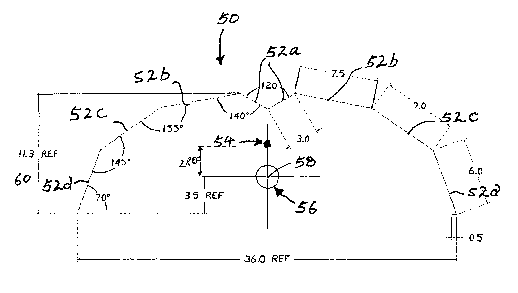
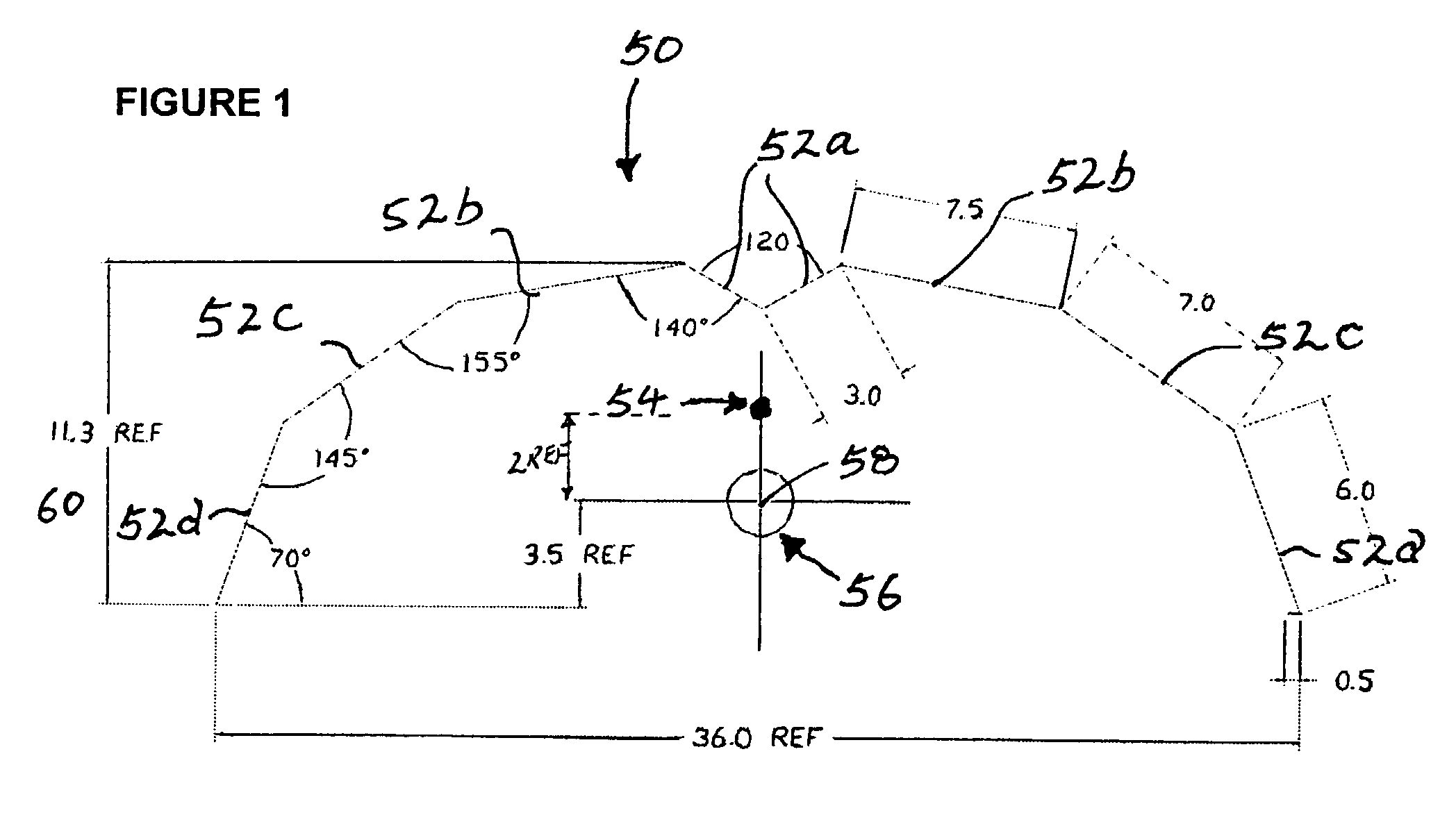
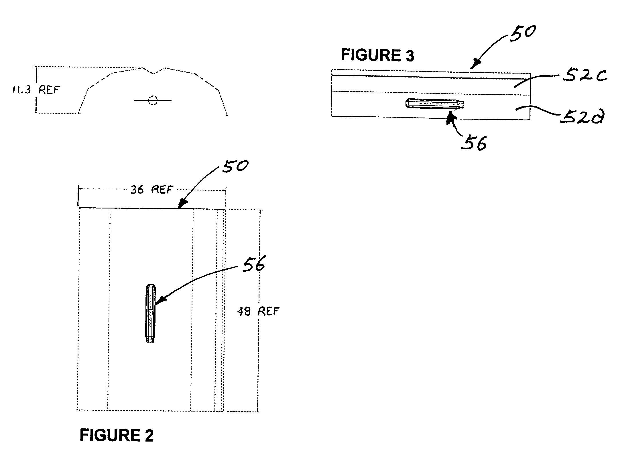
[0177]The present example compares the lighting characteristics of another improved lighting apparatus of the present invention comprising an elongated reflector means with a substantially elliptical cross section and a V-shape rib integral as illustrated in FIGS. 1 to 3.

[0178]For baseline measurements, the present elliptical lighting apparatus is tested with the same elongated light source (1000 W 250V S52 high pressure sodium LU1000 lamp with an E-25 clear tubular bulb) disposed longitudinally with its longitudinal center at the optical center of the elongated reflector means. FIGS. 18 illustrates a Candela polar plot for such a setup in which the 0° / Long line is relatively semi-circular implicating relative uniformity in longitudinal light emissions, while the 90° / Long line shows dramatic fluctuations which suggest uneven illumination and multiple “...


PUM


Abstract

An apparatus and method are provided for providing substantially uniform illumination. The apparatus includes an elongate reflector housing with an inner surface having a substantially constant profile in cross section which is generally concave, an optical center being defined at a geometric focus of the profile of the inner surface. In a preferred embodiment, substantially uniform illumination is achieved by providing an elongate light source positioned within the elongate reflector housing such that a geometric center of the light source is situated preferably spaced outwardly from the optical center of the housing, away from the inner surface of the housing.

Description

FIELD OF THE INVENTION[0001]The present invention relates to lighting and illumination devices and more particularly to a method of use thereof for uniform lighting.BACKGROUND[0002]Light sources and lamp types are commonly characterized and compared by their ability to translate electrical power into usable visible light. The efficiency or efficacy of a lighting system can be measured as the amount of light emitted (in Lumens) divided by the amount of electricity used (in Watts). The quality of light is often considered with respect to the colour of light emissions in terms of chromaticity or correlated color temperature, which described the color or wavelength of light emitted from the lighting system measured in Kelvin, and color rendering index (CRI), which indicates the lighting system's ability to show colors naturally (e.g. of an object) measured in percentage.[0003]There exist a diverse variety of light sources which vary widely in their construction, efficiency, color charac...

Claims


Application Information

Patent Timeline
Patent Type & Authority Patents(United States)
IPC IPC(8): F21V7/09F21V7/00
CPCF21V7/005Y02B20/00
Inventor WITKOWSKI, IRENEUSZ
Owner PRAIRIE PLANT SYSTEMS
Why Eureka
Try Eureka