Cutting tool and cutting method using the cutting tool
- Summary
- Abstract
- Description
- Claims
- Application Information
AI Technical Summary
Benefits of technology
Problems solved by technology
Method used
Image
Examples
first embodiment
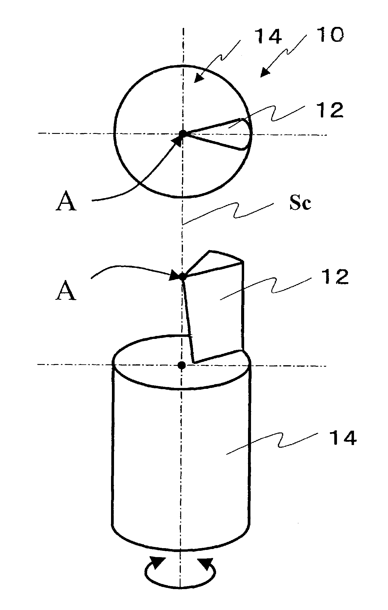
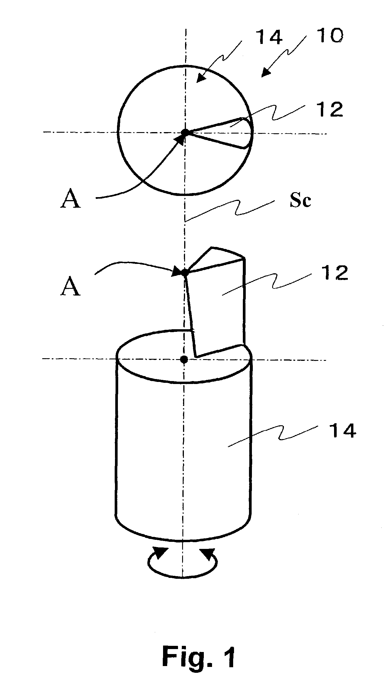
[0028]A cutting tool 10 which is mounted on a cutting machine according to the present invention is shown in FIG. 1. The cutting tool 10 is mounted on the spindle of the cutting machine. The cutting machine is provided with a motor for controlling the position of the spindle and a motor for controlling the position of a workpiece so to control a position (X, Y) of the spindle against the workpiece on a plane perpendicular to a spindle axis Sc. These X- and Y-axes are subject to feed control to perform planing by the cutting tool 10. The spindle is provided with a motor for controlling rotation (performing rotational control) of the cutting tool 10 in an arrow direction of FIG. 1 and a motor for controlling the vertical movement in a direction of the spindle axis Sc.
[0029]Here, the cutting tool 10 has a rod shape, its upper end is a blade section 12, and the lower end is a holder section 14 for connection to the cutting machine in FIG. 1. The holder section 14 is inserted and fixed t...
second embodiment
[0037]Then, the cutting machine according to the present invention will be described.
[0038]A cutting tool 20 which is mounted on the cutting machine according to the second embodiment is shown in FIG. 5. A cutting edge B of a blade section 22 of the cutting tool 20 is disposed on the spindle axis Sc in the same way as in the first embodiment. In the second embodiment, the radius of the cutting edge B is in the horizontal direction, and the center of the radius at the tool tip is disposed on the spindle axis Sc. The curved part (the arc shape part) with the radius is a machining face which can cut a workpiece. Because the tool's tip has the radius, the life of the cutting edge is extended compared with that of the cutting tool 10 of the first embodiment, in which only one point of the cutting edge is used for cutting.
[0039]FIG. 6 is a diagram showing the movement of the cutting tool 20 when the spindle of the cutting machine is subject to feed control. At this case, the spindle's cen...
third embodiment
[0040]Next, the cutting machine according to the present invention will be described.
[0041]A cutting tool 30 to be mounted on the cutting machine according to the third embodiment is shown in FIG. 7. In the cutting tool 30, the tip on the cutting edge is formed a portion curving and the tip is formed a radius on any part of the cutting edge in the horizontal direction.
[0042]FIG. 8 is a schematic diagram showing the cutting tool 30 cutting a sidewall having a given inclination angle in the direction of the spindle axis (z-axis) against the X-axis and Y-axis. As cutting is performed by the cutting tool 30, an offset a of a horizontal component from a cutting point Pw of the machining shape to the spindle center line may be used for a command position of the locus of movement Cd of the spindle's center position in the X-axis and Y-axis directions, to thereby produce a locus of movement of a point. This point is offset by a distance a from the cutting point Pw of the programmed machinin...
PUM
| Property | Measurement | Unit |
|---|---|---|
| Angle | aaaaa | aaaaa |
Abstract
Description
Claims
Application Information
 - R&D
- Intellectual Property
- Life Sciences
- Materials
- Tech Scout
- Unparalleled Data Quality
- Higher Quality Content
- 60% Fewer Hallucinations
Browse by: Latest US Patents, China's latest patents, Technical Efficacy Thesaurus, Application Domain, Technology Topic, Popular Technical Reports.
© 2025 PatSnap. All rights reserved.Legal|Privacy policy|Modern Slavery Act Transparency Statement|Sitemap|About US| Contact US: help@patsnap.com


