
Method and apparatus for embedding motor error parameter data in a drive motor of a power driven wheelchair

a technology of power-driven wheelchairs and error parameter data, which is applied in the direction of dynamo-electric converter control, electronic commutator, multiple dynamo-motor starters, etc., can solve the problems of variable component orientation, timely and costly operation which needs improvement, and the inability to mount the rotor and stator components in a precise orientation to each other

Inactive Publication Date: 2006-01-24
INVACARE CORP
View PDF8 Cites 37 Cited by
  • Summary
  • Abstract
  • Description
  • Claims
  • Application Information

AI Technical Summary

Benefits of technology

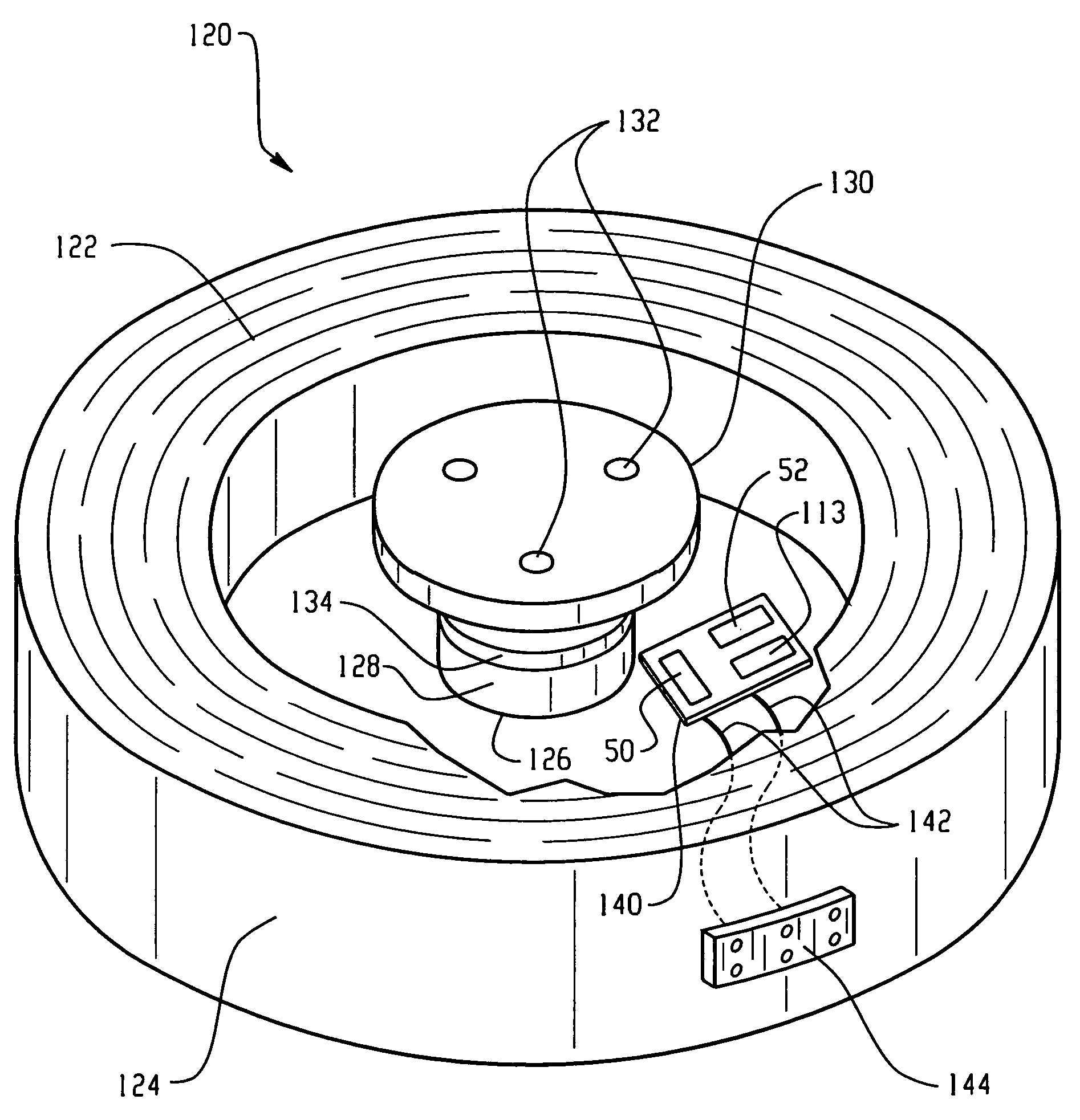
The present invention relates to a drive motor assembly for a power driven wheelchair. The assembly includes a stator housing with field coils and a sensor to detect motor rotation. The assembly also has a memory embedded in the stator housing to store motor error parameter data, which includes data of errors of the sensor. The motor controller can access the error parameter data to control the drive motor. The invention also includes a method of embedding motor error parameter data in the drive motor by controlling the motor through a predetermined drive pattern, sensing motor rotation during the drive pattern, and programming the memory with the derived error parameter data. The technical effects of the invention include improved accuracy and efficiency of the drive motor assembly for wheelchairs.

Problems solved by technology

However, mounting of the rotor and stator components in a precise orientation to each other may not always be accomplished.
While the motor components may be within their desired manufacturing tolerance, the orientation of such motor components during assembly of one motor to another may not be of the exact same dimensions which leads to variability of component orientation.
Thus, each time a service problem is encountered in the field involving replacement of a motor assembly unit, the calibration procedure has to be repeated which includes maintaining the wheels of the wheelchair off the ground through use of blocks or other onerous techniques.
Understandably, having to repeat the calibration procedure in the field to re-determine the motor error parameters each time a motor assembly is replaced is a very timely and costly operation which needs improvement.

Method used


Image

  • Method and apparatus for embedding motor error parameter data in a drive motor of a power driven wheelchair
  • Method and apparatus for embedding motor error parameter data in a drive motor of a power driven wheelchair
  • Method and apparatus for embedding motor error parameter data in a drive motor of a power driven wheelchair

Examples


Embodiment Construction

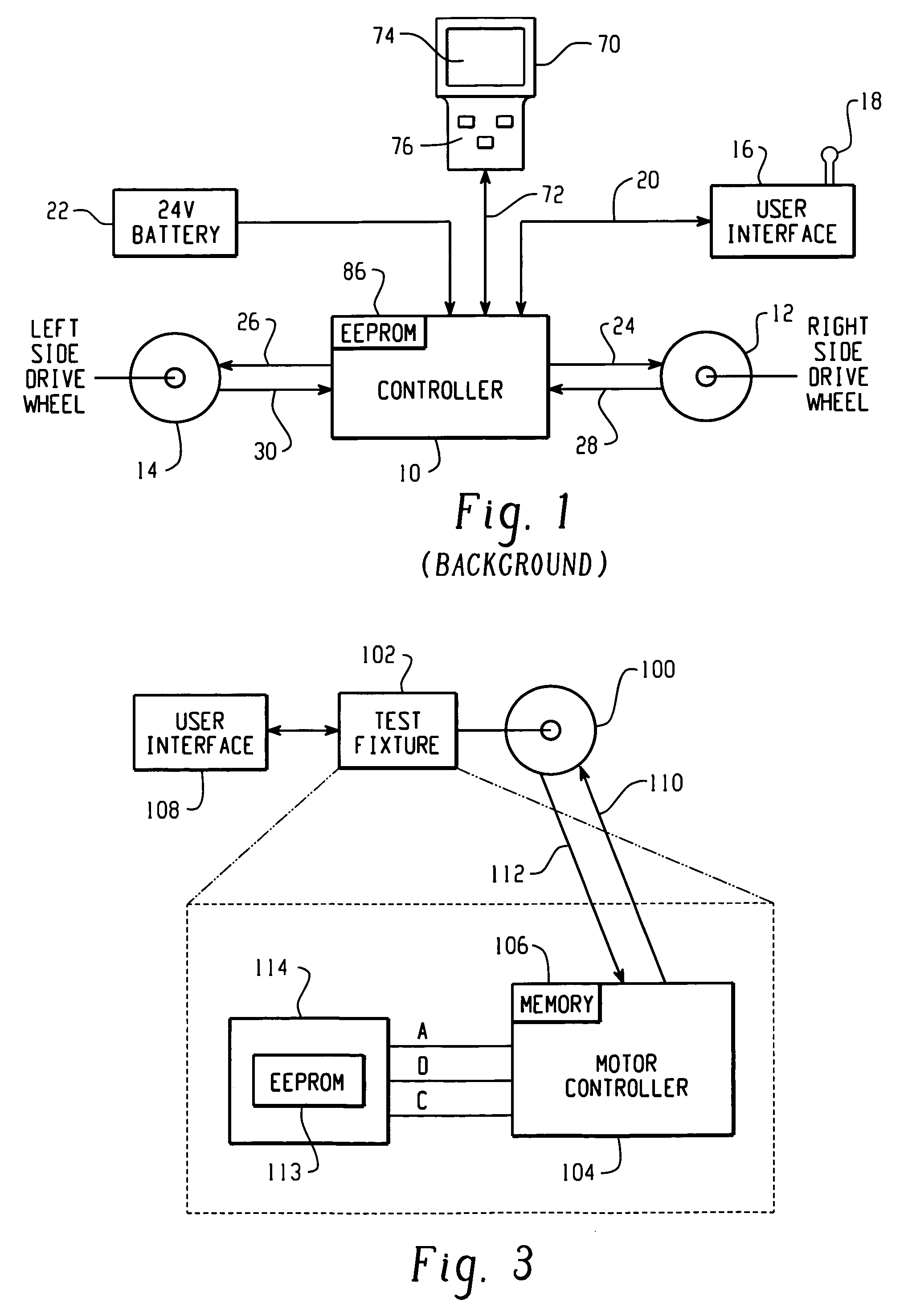
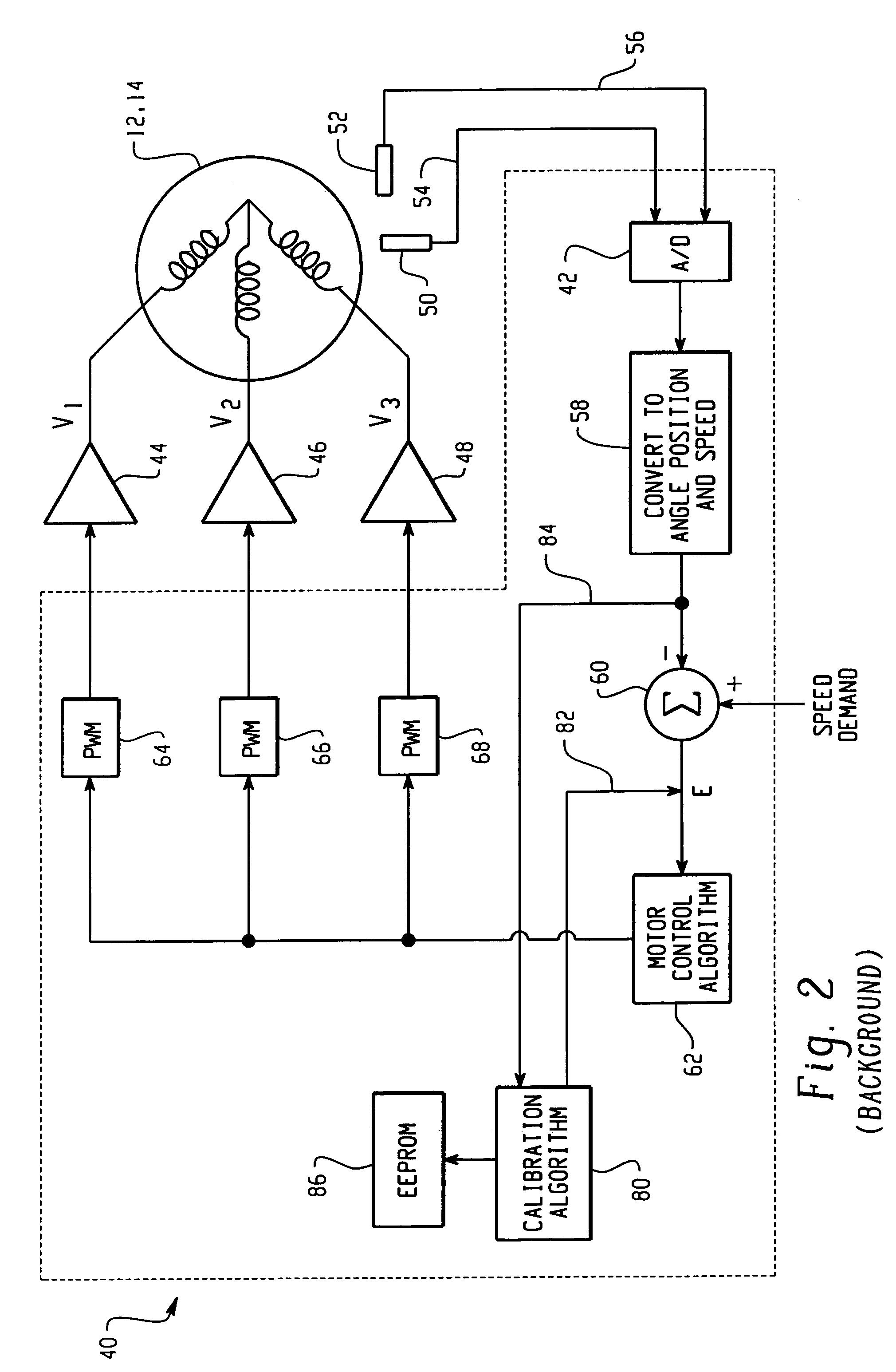
[0023]In accordance with the present invention, once a drive motor 100 has been assembled, it may be coupled to a test fixture 102 as shown in FIG. 3 so that the rotor thereof is free to rotate with respect to the stator when driven. The test fixture 102 may include a motor controller 104 which may be similar in design as the motor controller described in connection with FIG. 2. The motor controller 104 may include memory 106 for storing the operational programs of the control and calibration algorithms as described in the embodiment of FIG. 2 for controlling the motor under test 100. Tests may be performed on the assembled motor 100 through an interactive user interface 108 coupled to the test fixture 102. The user interface may be a personal computer (PC) with a conventional keyboard and display, or a manual control panel with pushbuttons and indicators, for example. In any event, once the motor 100 is attached to the test fixture 102 and free to rotate, an operator may control th...


PUM


Abstract

A drive motor assembly for a power driven wheelchair comprises: a stator housing for containing field coils of a stator of the motor assembly; at least one sensor disposed in the stator housing for sensing rotation of the motor; a memory storing motor error parameter data including data of errors of the at least one sensor, the memory being embedded in the stator housing; and a connection for accessing the error parameter data of the memory from the stator housing. The motor error parameter data may be accessed from the embedded memory of the drive motor by a programmed motor controller for use in controlling the drive motor. Also, the motor error parameter data may be embedded in the drive motor by the steps of: controlling the motor through at least one predetermined drive pattern; sensing motor rotation during the drive pattern and generating signals representative thereof; deriving error parameter data of the drive motor from the generated signals; programming a memory with the derived error parameter data; and embedding the memory in the drive motor.

Description

BACKGROUND OF THE INVENTION[0001]The present invention is directed to the field of power driven wheelchairs, in general, and more particularly, to a method and apparatus for embedding motor error parameter data in a drive motor of a power driven wheelchair.[0002]Power driven wheelchairs which may be of the type manufactured by Invacare Corporation of Elyria, Ohio, for example, generally include right and left side drive wheels driven by a motor controller via respectively corresponding right and left side drive motors, all of which being disposed on the wheelchair. An exemplary illustration of such a motor drive arrangement is shown in the schematic of FIG. 1. Referring to FIG. 1, a motor drive controller 10 which may be an Invacare MK IV™ controller, for example, controls drive motors 12 and 14 which are mechanically linked respectively to the right side and left side drive wheels of the wheelchair. A user interface 16 which may include a joystick 18 and selection switches (not sho...

Claims


Application Information

Patent Timeline
Patent Type & Authority Patents(United States)
IPC IPC(8): B60K1/00H02P5/46H02P6/16
CPCH02P6/00H02P6/16Y10S388/903H02P6/32
Inventor WAKEFIELD, II, THEODORE D.STROTHMANN, THOMASCURRAN, NEAL JOSEPH
Owner INVACARE CORP
Learn More