
Vehicular monitoring systems with a multi-window display

a monitoring system and multi-window technology, applied in the field of vehicles with multi-window displays, can solve the problems of damage to the bottom of the vehicle, no more realistic than seeing video images, and objects that pose a real threa

Active Publication Date: 2006-01-24
COLIGEN CHINA
View PDF3 Cites 67 Cited by
  • Summary
  • Abstract
  • Description
  • Claims
  • Application Information

AI Technical Summary

Benefits of technology

Enhances driver visibility and safety by covering all blind spots around large vehicles, providing accurate distance measurements and reducing the risk of damage from undetected objects, while simplifying system installation with wireless signal transmission.

Problems solved by technology

However, nothing is more realistic than seeing video images that actually present the road conditions.
Also, conventional back-up detectors mounted on a vehicle with elevated bumpers cannot detect objects lying below the detection zone, but these objects do pose a real threat.
If the vehicle runs over them unwarily, they can cause damage to the bottom of the vehicle.
However, the present design of these detection systems with video display are only suitable for passenger vehicles, and the detection systems have only one video camera.
Large vehicles, The shape and size of vehicle bodies of large vehicles cause large vehicles to have more blind spots than a passenger car.
Consequently, using one video camera to cover all possible angles is almost impossible.
Furthermore, simultaneously displaying the video from several video cameras presents a significant techical problem.
1. Hard-wired detector systems: Using several hard-wired detectors and video cameras creates complicated wiring configurations and raises the question of how to control multiple images from several video cameras on a common screen simultaneously.
2. Wireless detector systems: these detectors do away with much of the electrical wiring, but in the case where several video cameras use the same frequency band or nearby vehicles have wireless detectors with similar frequency bands, video degradation will occur due to mutual interference.

Method used


Image

  • Vehicular monitoring systems with a multi-window display
  • Vehicular monitoring systems with a multi-window display
  • Vehicular monitoring systems with a multi-window display

Examples


Embodiment Construction

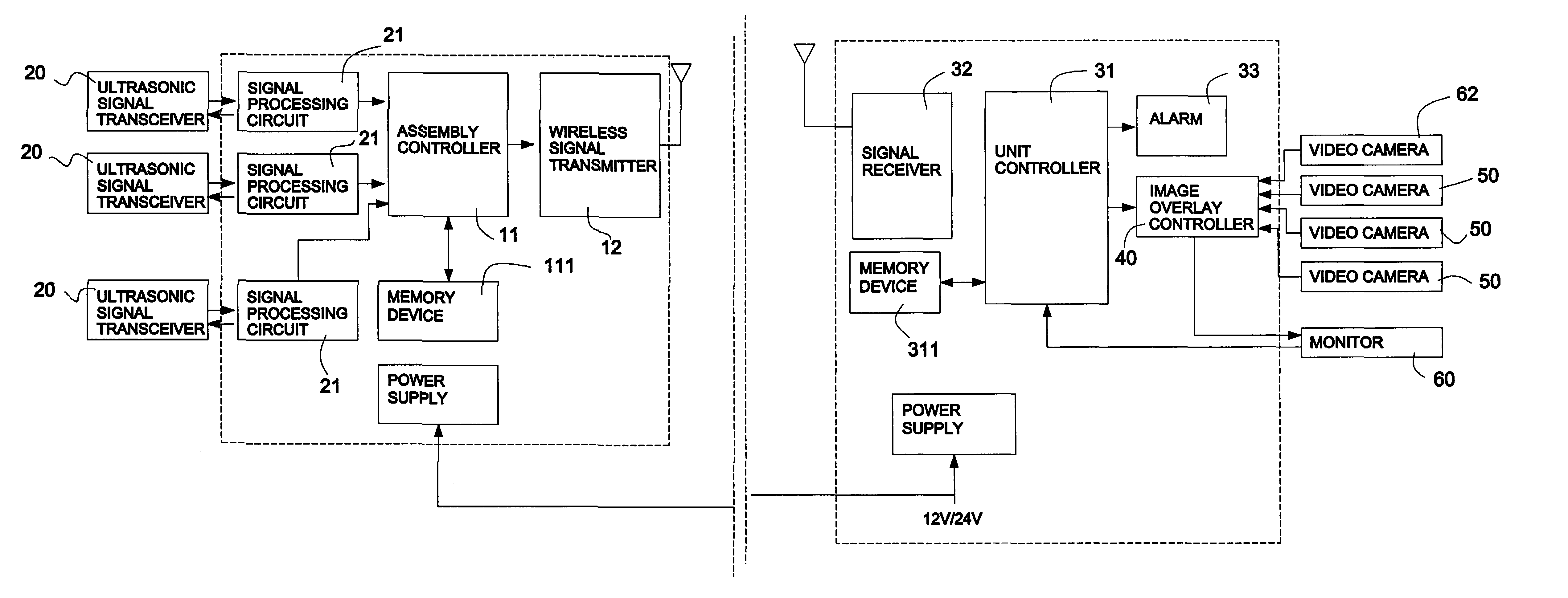
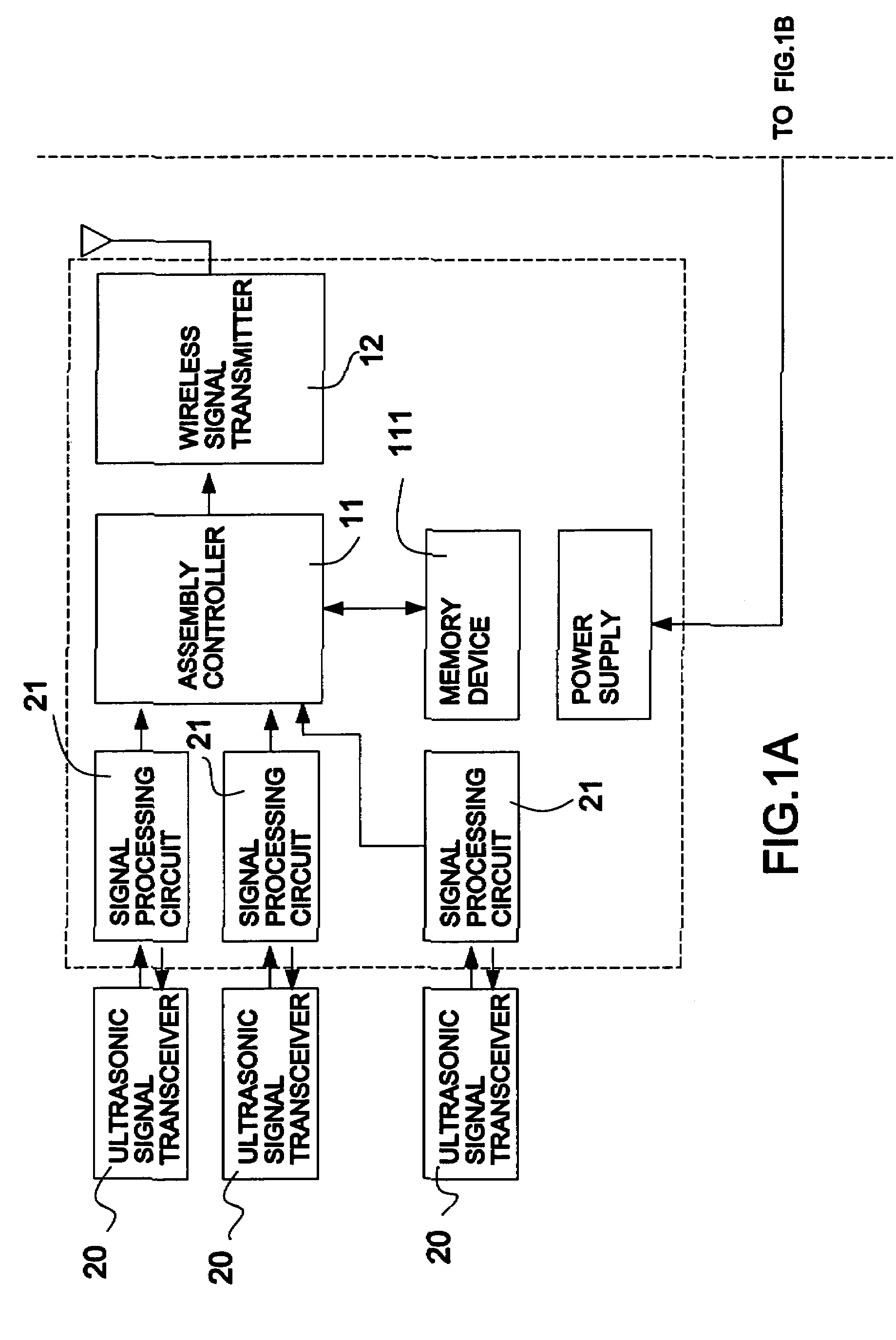
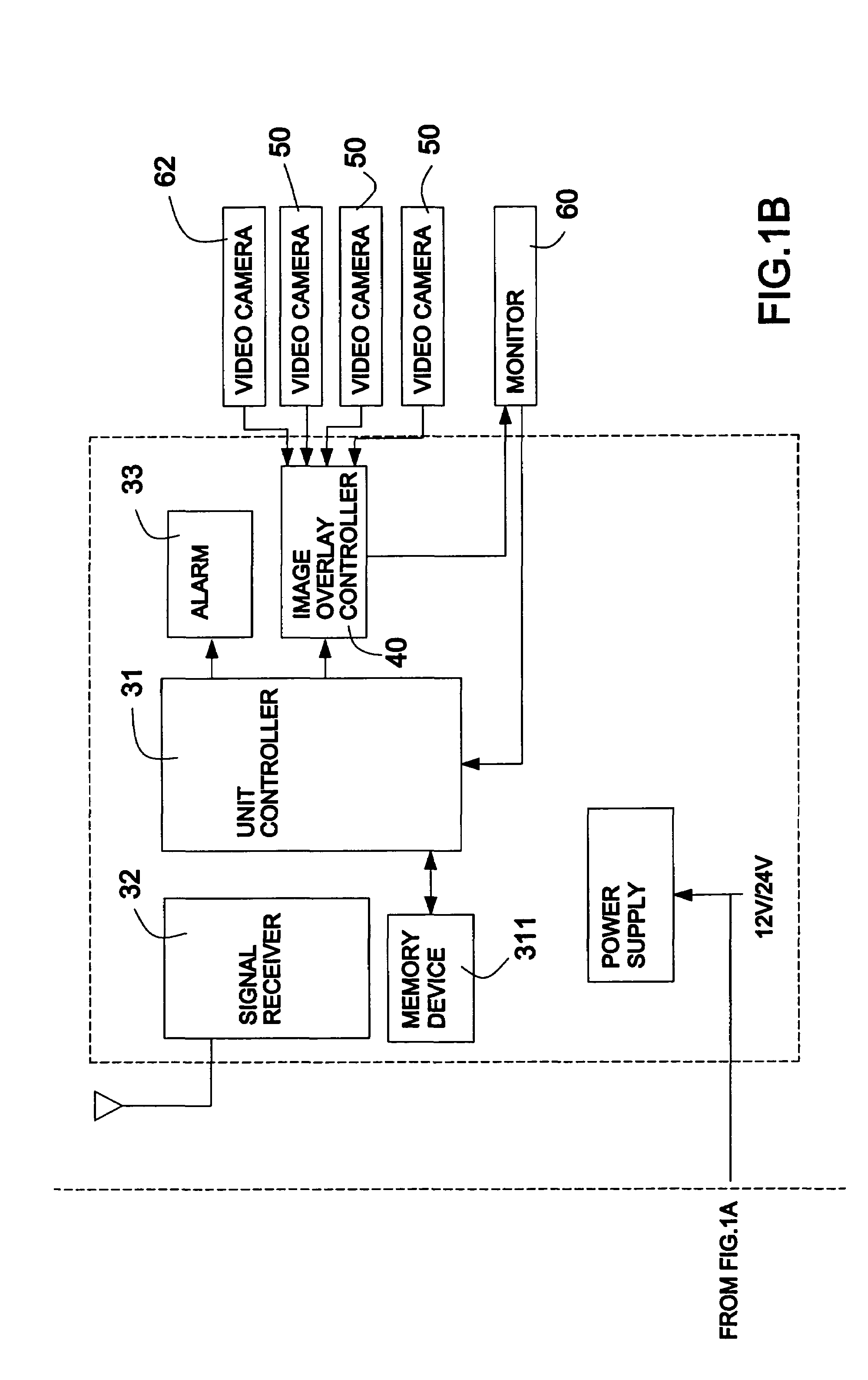
[0025]With reference to FIG. 1, the present invention provides a multi-window monitoring system installable on large vehicles. The system has more than one video camera (50) and multiple ultrasonic signal transceivers (20) installed at different locations on the large vehicle. The video cameras (50) can be installed at locations to cover usual blind spots when the vehicle makes a turn or is in reverse gear. The ultrasonic signal transceivers (20) can be installed on sides of the vehicle and on the vehicle bumpers to determine the distance to any object that the vehicle is approaching. An alarm (33) is initiated to warn the vehicle driver when the vehicle approaches an object within a preset threshold range.

[0026]The multi-window monitoring system comprises a data collection assembly (10), a console unit (30), multiple video cameras (50) and a monitor (60).

[0027]With further reference to FIGS. 2 and 3, the data collection assembly (10) comprises an assembly controller (11), a memory ...


PUM


Abstract

A multi-window vehicular monitoring system has a data collection assembly, a console unit and multiple video cameras. The data collection assembly uses RF signal transmission to send distance data, and the console unit is further connected to a monitor and several video cameras. The system employs an image overlay controller to correlate the distance data and images to produce single-channel or multiple-channel video signals. With a continuous display of video images from all angles and constantly updated distance data, the vehicle driver becomes more aware of conditions around the vehicle at any given time. Thus no blind spots exist for the driver around the vehicle. Using such a monitoring system, a driver's visibility and safety can be considerably enhanced under all driving conditions.

Description

BACKGROUND OF THE INVENTION[0001]1. Field of the Invention[0002]The present invention is related to a vehicular monitoring system with a multi-window display, and more particularly to a multi-window monitoring system that can help vehicle drivers monitor changing conditions in usual blind spots around the vehicle using multiple video cameras and ultrasonic signal transceivers.[0003]2. Description of Related Art[0004]Currently back-up detectors are becoming standard equipment in most passenger vehicles. The back-up detector is used to check the distance between the vehicle and any object behind the vehicle when the vehicle is in the reverse gear. The electronic detector has an array of ultrasonic sensors on the bumper which is connected to the gear box control circuitry and an alarm. When the vehicle is in the reverse gear and an object appears in the preset warning range, the electronic detector will initiate the alarm to warn the vehicle driver. Therefore, this is an effective safe...

Claims


Application Information

Patent Timeline
Patent Type & Authority Patents(United States)
IPC IPC(8): B60Q1/00H04N5/262H04N7/18
CPCH04N7/181H04N5/2624B60K2350/2013B60K2360/21
Inventor LI, SHIH-HSIUNG
Owner COLIGEN CHINA
Learn More