Short-range radar system with variable pulse duration

a short-range radar and variable pulse duration technology, applied in pulse techniques, instruments, measurement devices, etc., can solve the problem of reducing spatial selectivity in the second, and achieve the effect of extending the range of distance of a short-range radar system

Inactive Publication Date: 2006-01-24
ROBERT BOSCH GMBH
View PDF6 Cites 12 Cited by
  • Summary
  • Abstract
  • Description
  • Claims
  • Application Information

AI Technical Summary

Benefits of technology

[0011]The invention makes possible a broadening of the range of distance of a short-range radar system through a change of the HF-pulse width as a function of the sensed distance region. In this manner, the maximum range of distance of a short-range radar system is able to be increased up to 14 m or also to 30 m.
[0013]The enlargement of the HF-pulse width results in an increased distance range in connection with a smaller spatial selectivity. The reduced spatial selectivity in the second distance range, however, is not disadvantageous, since, based on the larger distance from obstacles in the second distance range for the various driver assistance systems, also only a minimal selectivity is required.

Problems solved by technology

The reduced spatial selectivity in the second distance range, however, is not disadvantageous, since, based on the larger distance from obstacles in the second distance range for the various driver assistance systems, also only a minimal selectivity is required.

Method used


Image

  • Short-range radar system with variable pulse duration
  • Short-range radar system with variable pulse duration
  • Short-range radar system with variable pulse duration

Examples


Embodiment Construction

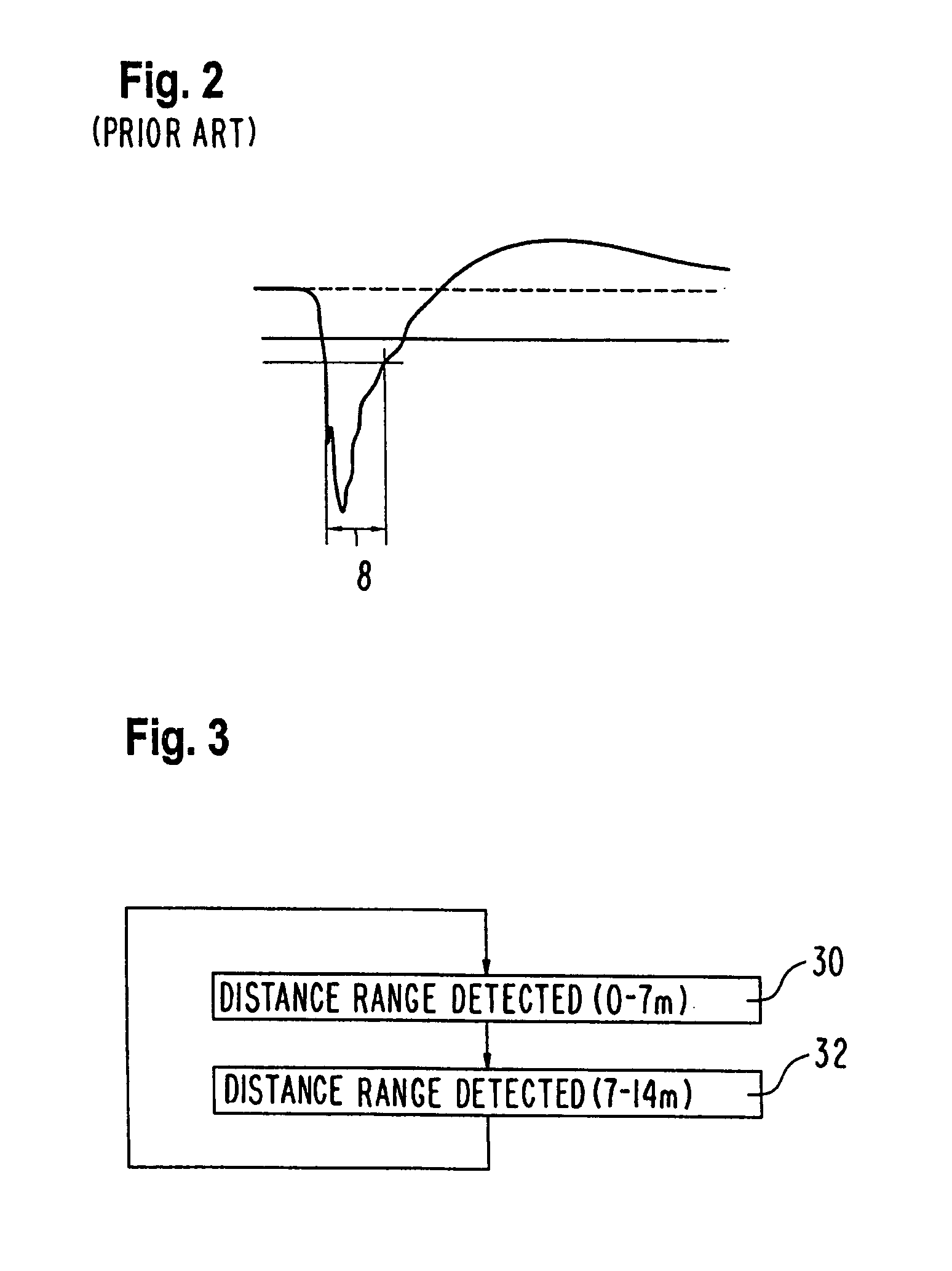
[0021]FIG. 3 shows a flow diagram for operating a short-range radar system. In step 30, the distance region of 0 m to 7 m in the detection region is sensed by the radar sensor of the short-range radar system. This takes place with a fixed impulse width, for example, of 400 ps, as is known in the state of the art.

[0022]In step 32, a further distance range, for example, of 7 m to 14 m is detected by the short-range radar sensor. In this second distance range, the detection takes place with an enlarged pulse width. For example, for the entire second detection range, a fixed, longer impulse width is selected. Preferably, the impulse width varies within the second distance region, for example, linearly increases with increasing distance.

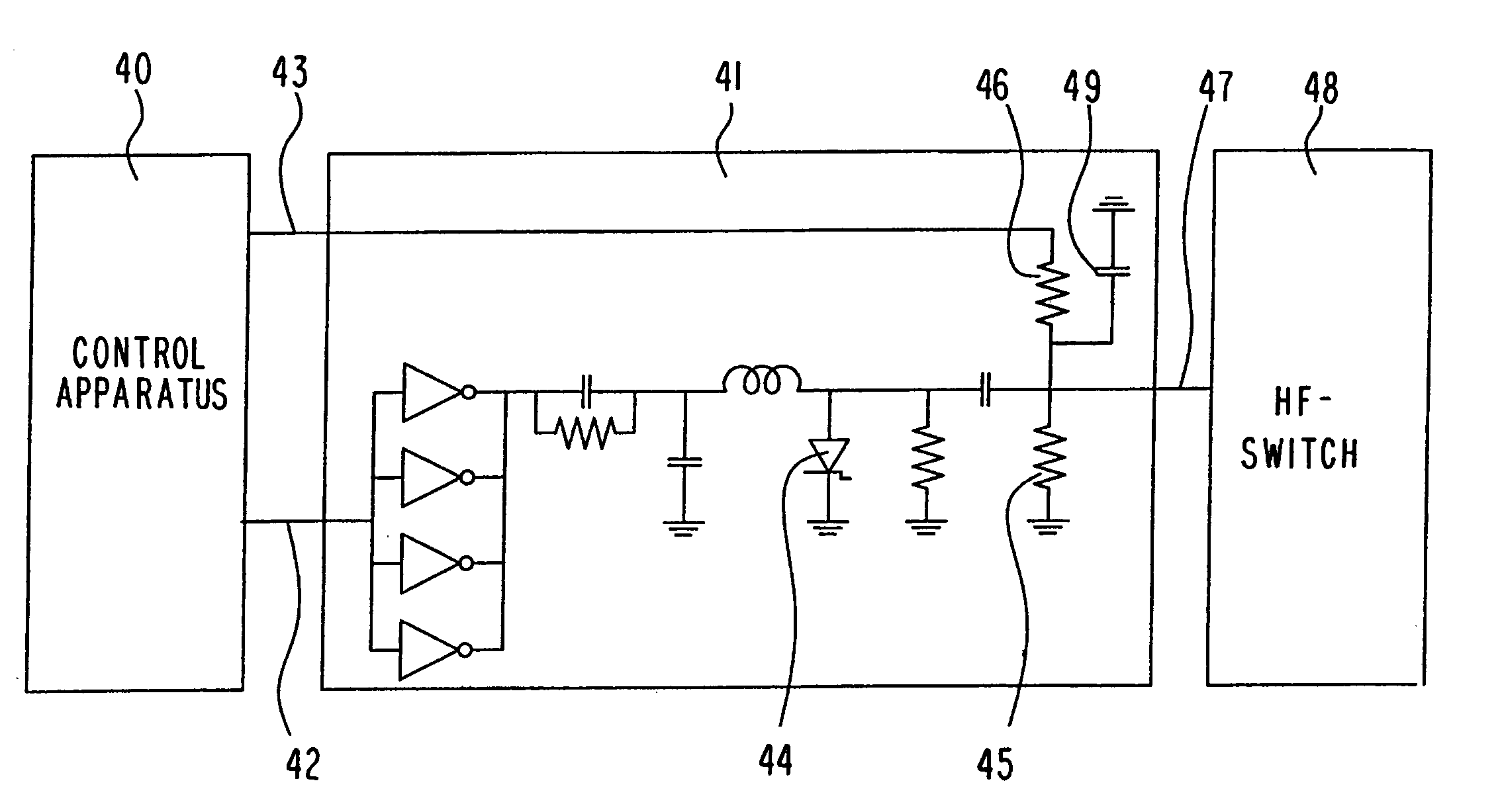
[0023]FIG. 4 shows a block diagram of an embodiment of an inventive short-range radar system. The short-range radar system includes a control apparatus 40, which controls an HF-impulse generator 41. The HF-impulse generator 41 has an input 42 for informat...


PUM


Abstract

A short-range radar system includes short-range radar sensor means and means (41) for HF-impulse generator for the sensor means. The means for HF-impulse generation are embodied for emitting impulses with adjustable pulse duration (51, 53).

Description

BACKGROUND OF THE INVENTION[0001]The present invention relates to a short-range radar system as well as a method for operating a short-range radar system.[0002]From the state of the art, short-range radar systems for various automobile uses are known. The corresponding radar sensors operate according to the pulse-echo principle: an electromagnetic pulse of approximately 400 ps duration is emitted from the radar sensor; in the area surrounding the vehicle, the pulse contacts another vehicle, a limiting wall, or another obstacle, for example. The pulse reflected on the obstacle is detected and evaluated. The running time of the pulses and the frequency shift based on the Doppler Effect are the essential measured quantity, from which the distance and relative speed are determined.[0003]At very close range, the pulse-echo measurement is operated with a center frequency of approximately 24 GHz. In this manner, the detection range around the sensor is subdivided into spherical layers, whi...

Claims


Application Information

Patent Timeline
Patent Type & Authority Patents(United States)
IPC IPC(8): G01S13/10G01S13/22G01S7/282H03K3/33
CPCG01S7/282H03K3/33G01S13/106
Inventor STEINBUCH, DIRK
Owner ROBERT BOSCH GMBH
Why Eureka
Try Eureka