Quasi-resonant DC-DC converters with reduced body diode loss

a diode converter and diode current technology, applied in the field of buck dc — dc converters, can solve the problems of reverse recovery loss, reduced energy efficiency of buck converters, and substantial energy loss of diode current, so as to reduce switching losses, reduce output voltage, and increase the duty cycle

Inactive Publication Date: 2006-01-24
VIRGINIA TECH INTPROP INC +1
View PDF3 Cites 70 Cited by
  • Summary
  • Abstract
  • Description
  • Claims
  • Application Information

AI Technical Summary

Benefits of technology

[0010]In an alternative embodiment, the circuit has coupled inductors. The coupled inductors are connected in series and in series with the resonant inductor. The resonant capacitor and synchronous switch are connected to a midpoint of the coupled inductors. In this embodiment, the coupled inductors tend to reduce output voltage, and thereby allow a greater duty cycle and consequently, provide reduced switching losses and greater efficiency.

Problems solved by technology

Body diode current produces substantial energy loss due to the forward-bias voltage drop across the diode, thereby reducing the energy efficiency of the buck converter.
Additionally, reverse recovery loss occurs when the body diode later becomes reverse-biased.
However, energy loss from both body diode conduction and reverse recovery increase dramatically with increasing operating frequency.
In this way, body diode conduction and reverse recovery tend to limit the maximum operating frequency of buck converters.
Also, state of the art microprocessors and digital electronics require exceptionally low supply voltages at high current.
However, a high voltage step-down ratio is typically accomplished by reducing the duty cycle of the buck switches, which tends to increase switching losses.
The switching losses are also increased by high frequency operation.
Hard switching results in large switching loss and reduced reliability of the switches.

Method used


Image

  • Quasi-resonant DC-DC converters with reduced body diode loss
  • Quasi-resonant DC-DC converters with reduced body diode loss
  • Quasi-resonant DC-DC converters with reduced body diode loss

Examples


Embodiment Construction

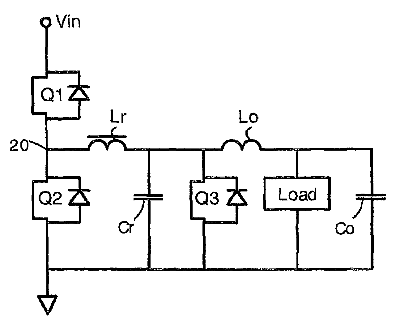
[0026]The present invention provides a buck converter having a resonant capacitor and resonant inductor. In operation, the resonant capacitor and inductor apply voltage and current across the switches so that soft switching (or nearly-soft switching) is provided. Also, the resonant capacitor and resonant inductor help to transfer output power. Body diode current loss is reduced in the present buck converters. Specifically, the resonant capacitor and resonant inductor apply a reverse current through the body diodes of the buck switches at turn-on so that zero-voltage switching (ZVS) is provided. Also, the resonant capacitor and inductor oppose current flow through buck switches at turn-off so that near-zero current switching (ZCS) is provided. Also, in one embodiment, a coupled inductor provides for reduced output voltage even with relatively high duty cycle. Additionally, an isolated embodiment is provided.

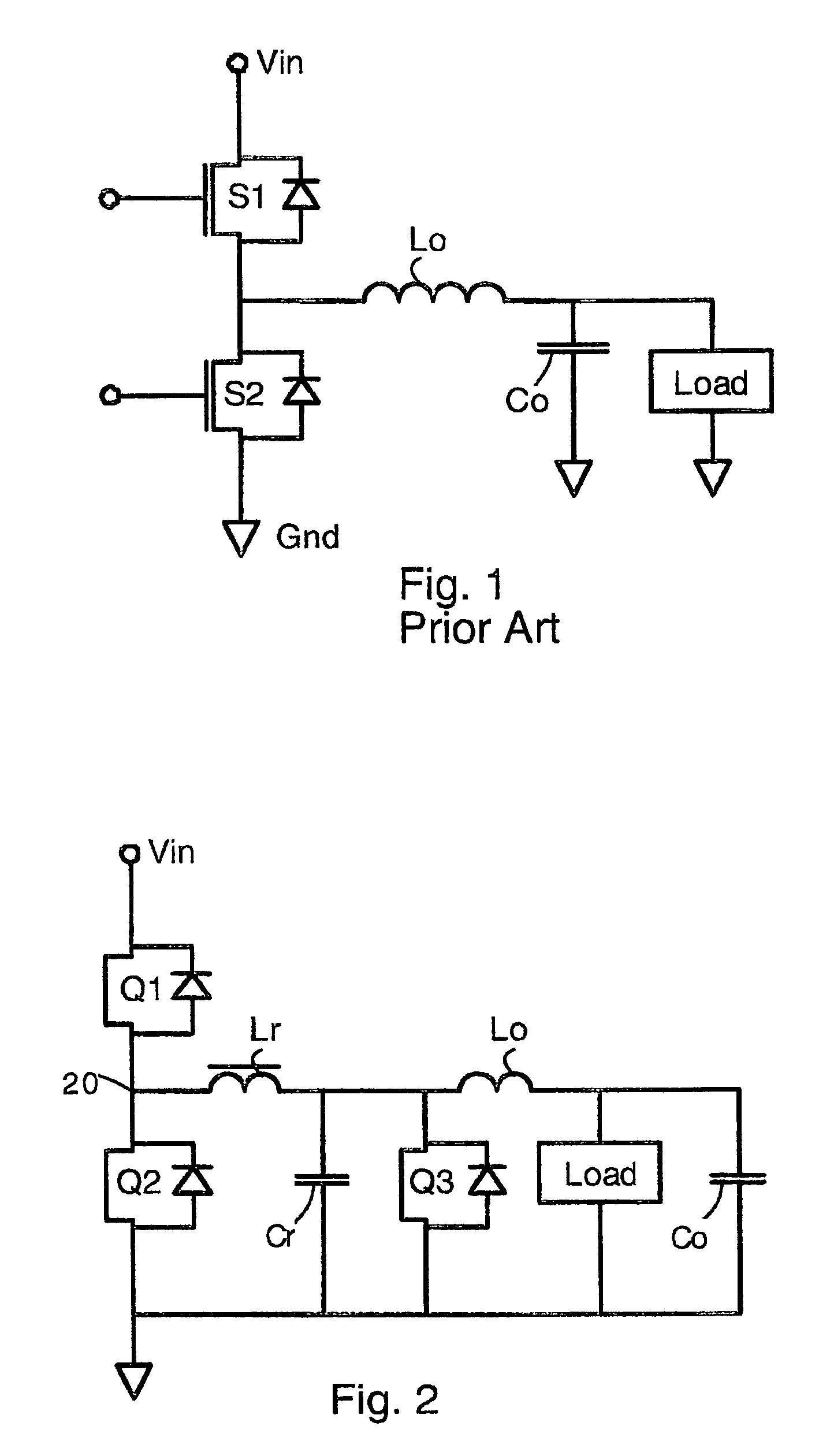
[0027]FIG. 1 shows a buck converter according to the prior art. The buck conv...


PUM


Abstract

Buck converters having a resonant inductor Lr, resonant capacitor Cr, and synchronous switch Q3 that together provide reduced switching loss and soft switching. In operation, the resonant inductor Lr is charged during a time period A. Then, Lr is freewheeling and provides current to an output inductor Lo. Then, Q3 is turned OFF, and energy from the resonant inductor Lr charges the resonant capacitor Cr. Finally, energy from the resonant capacitor Cr is provided to the output inductor and load. The output power can be adjusted by phase control of the operation of switch Q3. In alternative embodiments, the circuit has a pair of coupled inductors L1 L2 or an isolation transformer 40. The coupled inductors have a polarity selected so that the output voltage is reduced, thereby allowing top switch Q1 to have a greater duty cycle. These circuits feature no body diode loss in the switch Q3.

Description

FIELD OF THE INVENTION[0001]The present invention relates generally to electrical power supplies. More particularly, it relates to buck DC—DC converters having a resonant capacitor and resonant inductor that provide increased efficiency and reduced output voltage.BACKGROUND OF THE INVENTION[0002]Buck converters are commonly used in electronics for changing the voltage or polarity of a power supply. They are often used to provide low voltage, high current output power. Buck converters typically employ two electronic switches (typically MOSFETs) in combination with an output inductor. The switches are alternately turned on, thereby providing voltage pulses to the output inductor.[0003]During portions (dead times) of the switching cycle, both switches are off. When both switches are off, the output inductor produces freewheeling current that flows through the integral body diode of one of the switches. Body diode current produces substantial energy loss due to the forward-bias voltage ...

Claims


Application Information

Patent Timeline
Patent Type & Authority Patents(United States)
IPC IPC(8): H02M3/335H02M3/158
CPCH02M3/158H02M3/33576Y02B70/1433Y02B70/1425Y02B70/10
Inventor XU, MINGLEE, FRED C.
Owner VIRGINIA TECH INTPROP INC
Why Eureka
Try Eureka