Hybrid car

Inactive Publication Date: 2006-01-31
HITACHI LTD
View PDF30 Cites 41 Cited by
  • Summary
  • Abstract
  • Description
  • Claims
  • Application Information

AI Technical Summary

Benefits of technology

[0010]The above first object of the present invention can be achieved by allowing a lean burn to take place to enlarge the region of the highly efficient operation and increasing the proportion of operation with the engine at a low torque while decreasing the proportion of moto

Problems solved by technology

In the high engine speed region, driving performance takes precedence over other

Method used


Image

  • Hybrid car
  • Hybrid car
  • Hybrid car

Examples


Embodiment Construction

[0051]Embodiments of the present invention will be described hereinunder with reference to the drawings.

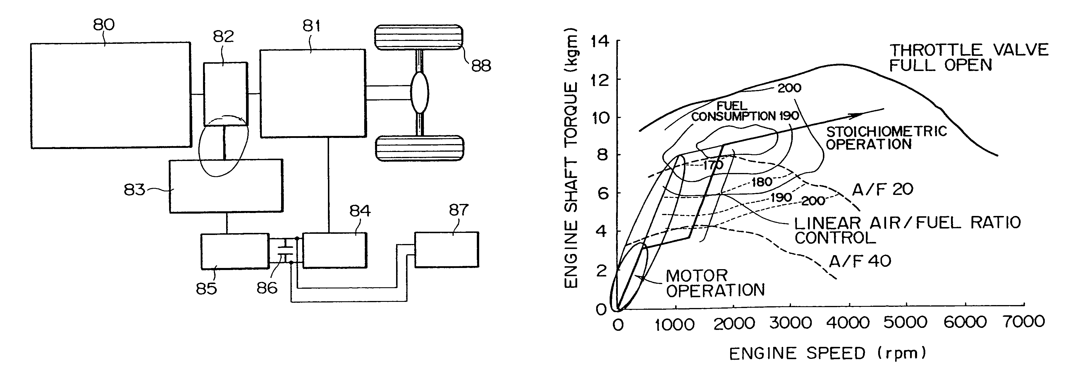
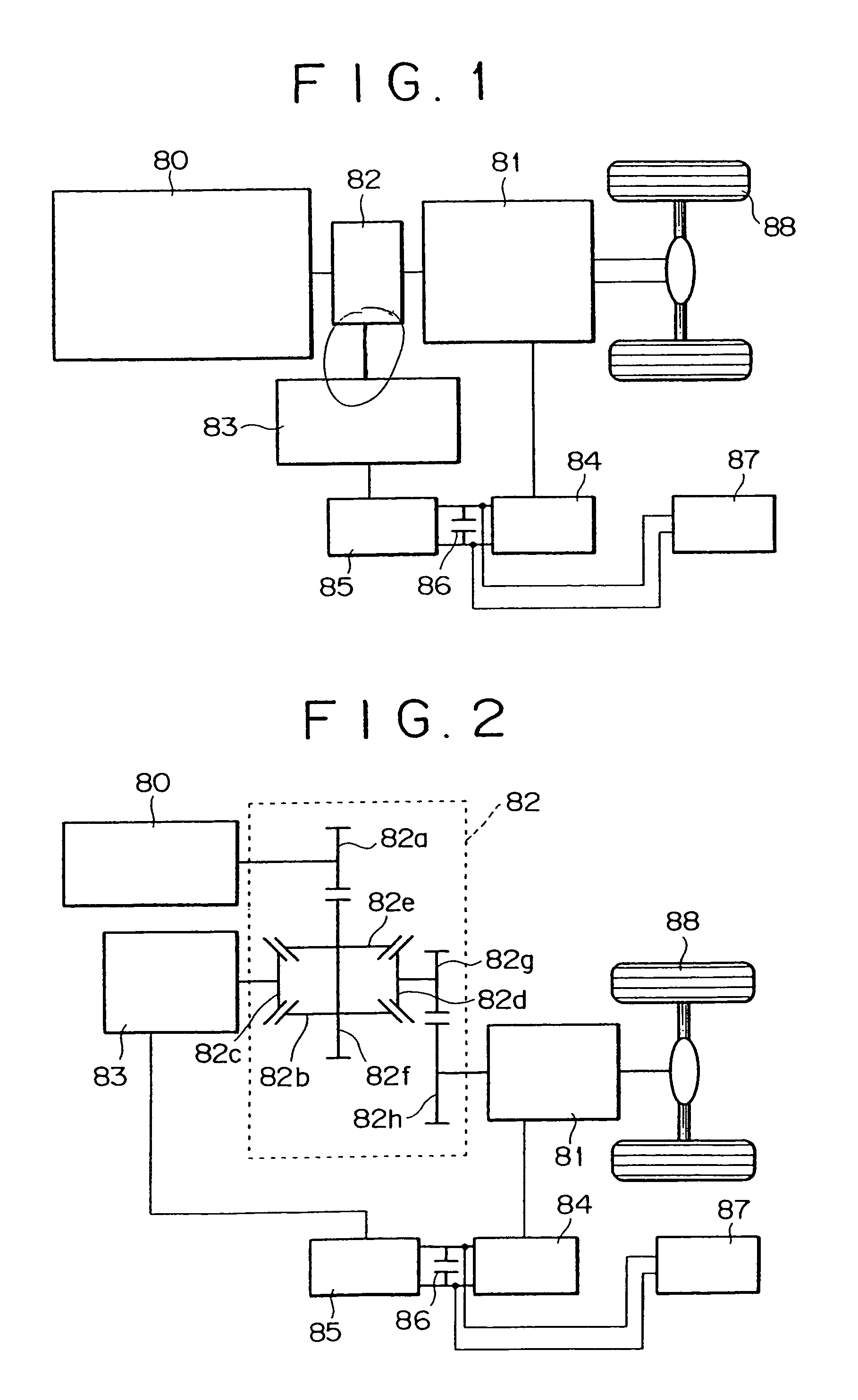
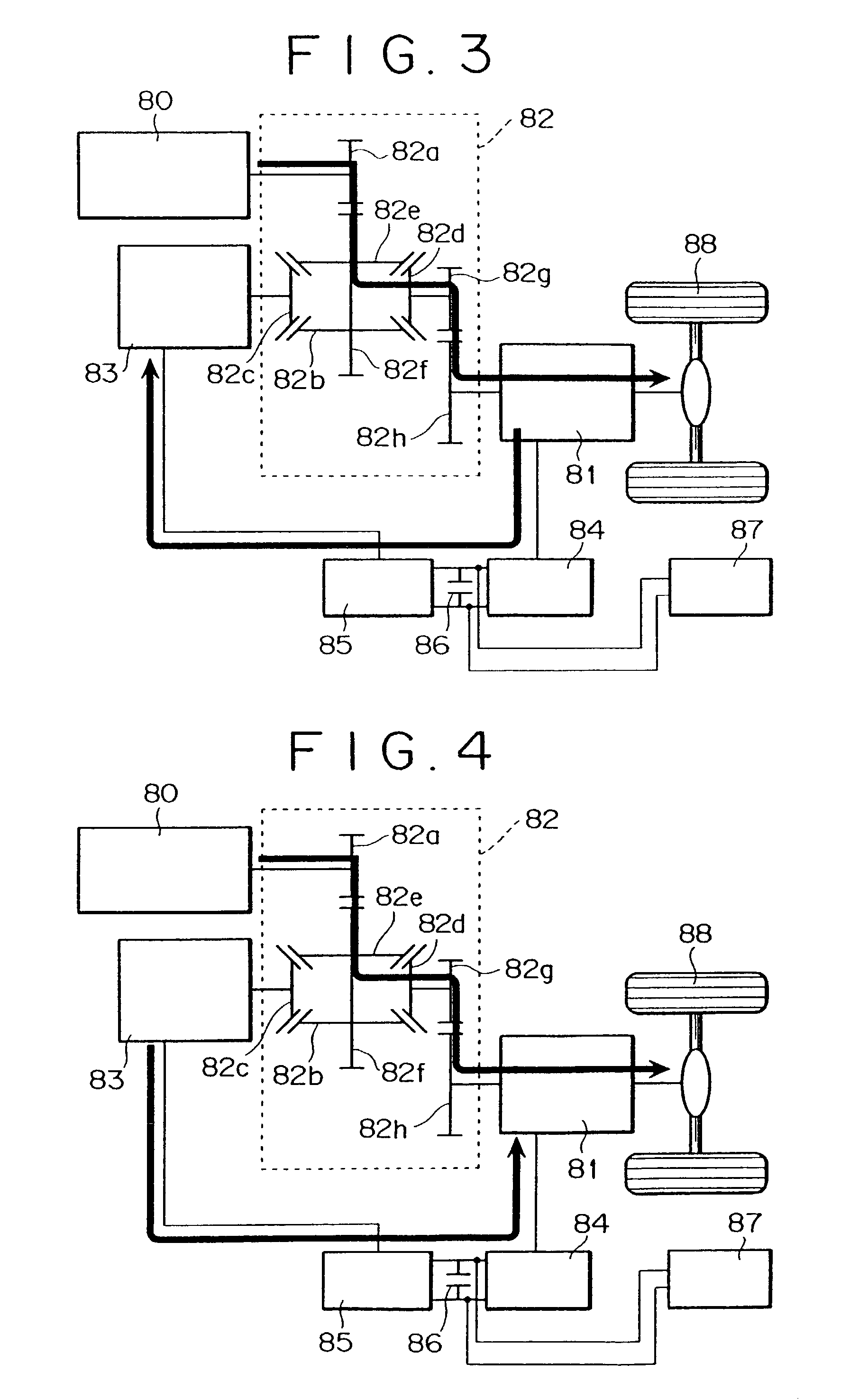
[0052]FIG. 1 illustrates a system configuration according to the present invention. The system comprises an engine 80, a drive assisting motor generator 81, a differential motor generator 83, a power distributing mechanism 82, a battery 87, a smoothing condenser 86 and inverters 84, 85. As the engine 80 is it desirable to use a cylinder-direct fuel injection type engine which can control the output of the engine by the air / fuel ratio. In the cylinder-direct fuel injection type engine, fuel is injected directly into a cylinder and the mixture distribution can be controlled, so it is possible to perform an ultra-lean burn operation. Driving wheels 88 are controlled by the engine 80, the driving assisting motor generator 81, and the differential motor generator 83. The driving torque distribution is con trolled so as to maximize the engine efficiency. The engine and the motors are co...


PUM


Abstract

By a lean burn operation, a highly efficient operation region is enlarged, the proportion of engine operation in a low torque condition is increased, and the proportion of motor operation using a battery is decreased. It is possible to provide a hybrid car of an engine-electric motor configuration which can effect a highly efficient operation without increasing the capacity of motor and that of battery.

Description

[0001]This application is a continuation of application Ser. No. 09 / 891,273, filed Jun. 27, 2001, now abandoned which is a divisional of application Ser. No. 09 / 646,521, filed Nov. 27, 2000, which is a 371 of PCT / JP99 / 01398, filed Mar. 19, 1999 now abandoned.TECHNICAL FIELD[0002]The present invention relates to an apparatus and method for controlling a hybrid car having an engine and electric motors.BACKGROUND ART[0003]In a hybrid car using an engine and electric motors, a power generated by the engine is converted to an electric energy directly or through a generator, while the electric energy is converted to a mechanical energy by a motor or is stored in a battery. Such a hybrid car is advantageous in that the running distance can be made long in comparison with an electric car in which the supply of energy is done with a battery alone.[0004]In Japanese Patent Laid-Open No. Hei 9-37410 there is disclosed a configuration provided with an engine, a power distributing mechanism, and ...

Claims


Application Information

Patent Timeline
IPC IPC(8): B60K1/00B60T7/12F02D13/00B60L50/10B60K6/445B60K6/48B60K6/543B60L50/15B60W10/06B60W10/08B60W10/10B60W10/26B60W20/00F01N3/08F02D13/02F02D29/02F02D41/02
CPCB60K6/445B60L11/12B60W10/06B60W10/08B60W10/26B60W20/00F01N3/0842F02D41/028Y02T10/6239B60L2240/486B60W2510/0604B60W2710/0622B60W2710/105F01N2570/04F02D2250/24Y02T10/54Y02T10/56Y02T10/6286Y02T10/7005Y02T10/7077Y10S903/945B60W2510/305B60K2001/003B60L50/15Y02T10/40Y02T10/62Y02T10/70Y02T10/7072
Inventor NOGI, TOSHIHARUSHIRAISHI, TAKUYAOOSUGA, MINORUTOKUYASU, NOBORUNAKAYAMA, YOKO
Owner HITACHI LTD
Why Eureka
Try Eureka