

Hybrid-vehicle drive system with torque increasing device and driving method thereof
- Summary
- Abstract
- Description
- Claims
- Application Information
AI Technical Summary
Benefits of technology
Problems solved by technology
Method used
Image

Examples
first embodiment
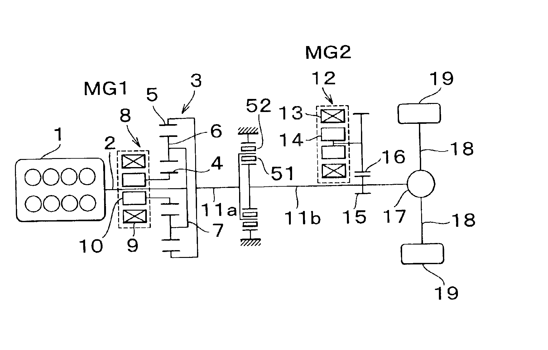
[0045]FIG. 3 is a schematic view of the hybrid vehicle driving system as shown in FIG. 1 in which an output shaft 2 of an internal combustion engine 1 is connected to a first motor-generator 8 and a wheel-drive shaft 11 via a power distribution mechanism 3 and a second motor-generator 12 is connected to the wheel-drive shaft 11 as in the drive system shown in FIG. 1. The drive system is provided with a torque increasing device that increases the cranking torque during cranking of the internal combustion engine 1 apart from the second motor-generator 12. Referring to FIG. 3, elements that are the same as or equivalent to those shown in FIG. 1 are denoted by the same reference numerals and characters. The drive system in accordance with the embodiment is provided with a clutch 51 at an intermediate portion of the wheel-drive shaft 11. The clutch 51 divides the wheel-drive shaft 11 into a first portion located near the cranking support torque increase device and a second portion locate...
second embodiment
[0048]FIG. 4 is a view schematically showing the invention in which the clutch 51 and the brake 52 of the drive system shown in FIG. 3 are replaced by a one-way clutch 53 and a one-way brake 54, respectively. In FIG. 4, elements that are the same as or equivalent to those shown in FIG. 1 are denoted by the same reference numerals and characters. When it is assumed that the internal combustion engine 1 is operated to rotate the output shaft 2 clockwise as viewed from the left side of FIG. 4, the ring gear 5 is driven counterclockwise as viewed from the left side of FIG. 4 by the reaction force generated by MG18 for cranking the internal combustion engine 1. When the one-way brake 54 is structured to prevent the first portion 11a of the wheel-drive shaft 11 from rotating in its rotating direction, the first portion 11a is allowed to rotate along the rotating direction of the internal combustion engine 1, and the reaction support required for the ring gear 5 is obtained only when MG18 ...
PUM
 Abstract
Description
Claims
Application Information