Process for the manufacturing of surface elements with a structured upper surface

a manufacturing process and surface structure technology, applied in the direction of printing process, decoration arts, building components, etc., can solve the problems of time-consuming and expensive processes, and achieve the effect of rearranging the décor

Inactive Publication Date: 2006-01-31
UNILIN NORDIC AB
View PDF22 Cites 191 Cited by
  • Summary
  • Abstract
  • Description
  • Claims
  • Application Information

AI Technical Summary

Benefits of technology

[0033]The décor may accordingly be obtained by making a high resolution or selected resolution digital picture of the desired décor. This is suitably made by means of a digital camera or scanner. The most common décor will of course be different kinds of wood and minerals like marble, as these probably will continue to be preferred surface decoration in home and public environments. It is, however, possible to depict anything that is visible. The digitised version of the décor is then edited to fit the size of the supporting core. It is also possible to rearrange the décor in many different ways, like changing colour tones, contrast, dividing the décor into smaller segments and adding other decorative elements. It is also possible to completely create the décor in a computer equipped for graphic design. It is possible to create a simulated décor so realistic that even a professional will have great problems in visually separating it from genuine material. This makes it possible to make for example floor boards with an almost perfect illusion of a rare kind of wood, like ebony or rose wood and still preserving trees under threat of extermination.

Problems solved by technology

The only way, so far, to achieve a surface structure in lacquer is casting or abrasive moulding which both are time consuming and expensive processes.

Method used


Image

  • Process for the manufacturing of surface elements with a structured upper surface
  • Process for the manufacturing of surface elements with a structured upper surface
  • Process for the manufacturing of surface elements with a structured upper surface

Examples


example 1

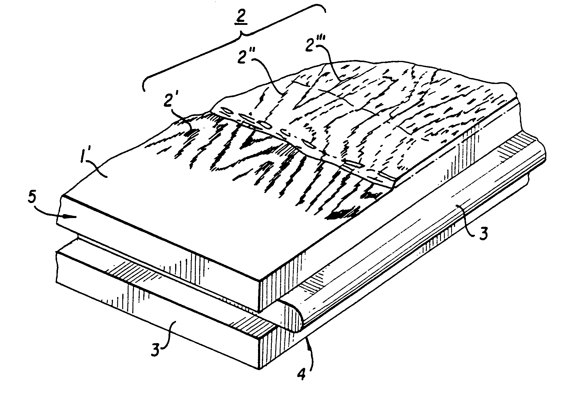
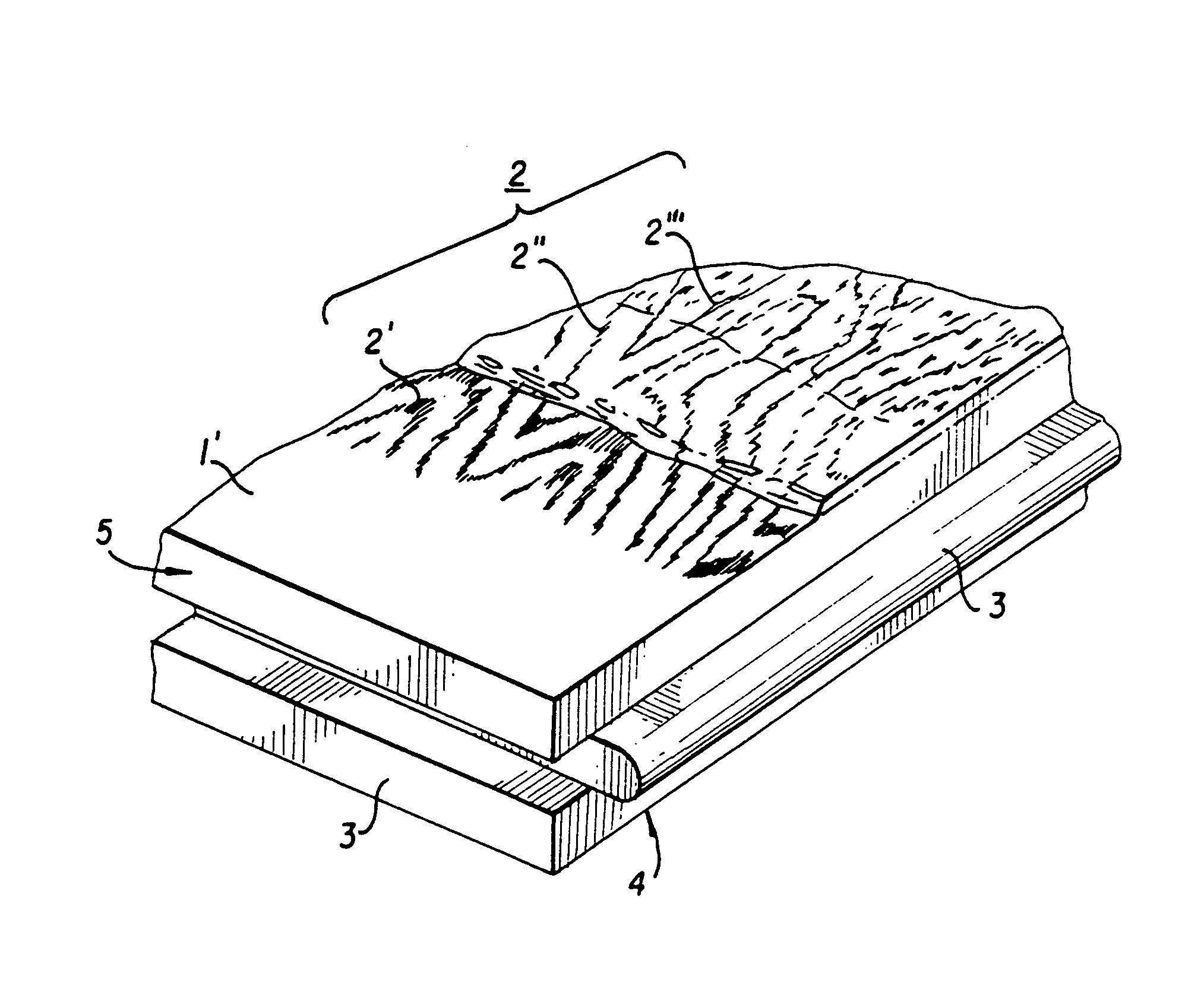
[0072]A supporting core of medium density fibre board were sanded smooth. A layer of primer lacquer were applied on top of the fibre board. The primer were cured after which a decor was printed on top of the primer.

[0073]The build up of a structured wear layer was then initiated by applying 10 g / m2 of UV-curing acrylic lacquer by means of roller coating. The surface structuring was then initiated by printing the part of the structure that is to form recesses in the finished surface. A UV-curing acrylic wetting repellent lacquer with a content of silicone polymer was printed by means of an ink-jet printer in the desired pattern. The pattern was made up by narrow lines of varying length and covered less than 2% of the total surface of the surface element. The wetting repellent lacquer was then exposed to a predetermined energy amount of UV-light so that it cured. 30 g / m2 of UV-curing acrylic lacquer by means of roller coating. The lacquer was repelled from the parts of the surface whe...

example 2

[0076]A supporting core of medium density fibre board were sanded smooth. A layer of primer lacquer were applied on top of the fibre board. The primer were cured after which a decor was printed on top of the primer.

[0077]The build up of a wear layer was then initiated by applying 30 g / m2 of UV-curing acrylic lacquer by means of roller coating. 20 g / m2 of hard particles made of α-aluminium oxide with an average particle size of 70 μm were sprinkled on the still sticky lacquer. The lacquer was then exposed to a predetermined energy amount of UV-light so that it cured only partly and the viscosity was increased. Another 30 g / m2 of UV-curing acrylic lacquer was then roller coated onto the already applied layer after which another 20 g / m2 of α-aluminium oxide particles with an average particle size of 70 μm were sprinkled on the still sticky second coating. The lacquer was then exposed to a predetermined energy amount of UV-light so that it cured only partly and the viscosity was increas...

example 3

[0081]A supporting core of medium density fibre board were sanded smooth. A layer of primer lacquer were applied on top of the fibre board. The primer were cured after which a decor was printed on top of the primer.

[0082]The build up of a structured wear layer was then initiated by applying 10 g / m2 of UV-curing acrylic lacquer by means of roller coating. The surface structuring was then initiated by printing the part of the structure that is to form recesses in the finished surface. A UV-curing acrylic wetting repellent lacquer with a content of silicone polymer was printed by means of an ink-jet printer in the desired pattern. The pattern was made up by narrow lines of varying length and covered less than 2% of the total surface of the surface element. The wetting repellent lacquer was then exposed to a predetermined energy amount of UV-light so that it cured. 15 g / m2 of UV-curing acrylic lacquer by means of roller coating. The lacquer was repelled from the parts of the surface whe...


PUM

PropertyMeasurementUnit
particle sizesaaaaaaaaaa
particle sizeaaaaaaaaaa
sizeaaaaaaaaaa

Abstract

A process for the manufacturing of a decorative surface element, which element comprises a base layer and a decorative upper surface. A wetting repellent lacquer is printed in a predetermined pattern on the decorative upper surface. The wetting repellent lacquer covers only parts of the decorative upper surface. A wear layer of a UV or electron beam curing lacquer is then applied on top of the decorative upper surface which UV or electron beam curing lacquer is repelled from the parts of the surface being covered by the wetting repellent lacquer whereby a surface structure is achieved.

Description

BACKGROUND OF THE INVENTION[0001]The present invention relates to a process for the manufacture of decorative surface elements with a surface structure matching the decor of the upper surface.DESCRIPTION OF THE RELATED ART[0002]Products coated with simulated versions of materials such as wood and marble are frequent today. They are foremost used where a less expensive material is desired, but also where resistance towards abrasion, indentation and different chemicals and moisture is required. As an example of such products floors, floor beadings, table tops, work tops and wall panels can be mentioned.[0003]As an example of an existing product can be mentioned the thermosetting laminate which mostly consists of a number of base sheets with a decor sheet placed closest to the surface. The decor sheet can be provided with a desired decor or pattern. Frequently used patterns usually represent the image of different kinds of wood or minerals such as marble or granite. The surface of the ...

Claims


Application Information

Patent Timeline
Patent Type & Authority Patents(United States)
IPC IPC(8): B05D3/06B05D1/36B05D1/38B05D7/26E04F15/10B32B5/30B32B29/00B41M1/26B41M3/00B41M7/00B44C3/08B44C5/04B44D2/00B44D3/00B44F1/06B44F9/02B44F9/04E04B9/04E04B9/32E04F13/08E04F13/16E04F13/18E04F15/02
CPCB32B5/30B32B29/00B41M1/26B41M3/00B44C3/085B44C5/04B44C5/0446B44C5/0469B44C5/0476B44C5/0492B44D2/00B44D3/003B44F1/06B44F9/02B44F9/04E04B9/0435E04B9/045E04B9/32E04F13/0871E04F13/16E04F13/18E04F15/02B27N7/005B41J3/4073E04F15/02038E04F15/105E04F15/107B32B7/00Y10T428/24388B32B38/145B32B2037/243B32B2038/0076B32B2307/554B32B2471/00B41M3/006B41M7/0027B41M7/0045E04F2201/0107E04F2201/023Y10T428/24455Y10T428/24595Y10T428/24479Y10T156/1039Y10T428/2462Y10T428/2443Y10T428/24876Y10T428/24802Y10T428/24372Y10T428/24438Y10T428/24364Y10T428/24653B32B38/06B32B38/08B32B5/24B32B2307/414B32B2260/046B32B7/04B32B2260/02B32B2607/02B44C3/02B44C3/08B41J2/21B41J3/407B41J11/0015E04F13/072
Inventor HANSSON, KRISTERLUNDGREN, JOHANWERNERSSON, HAKAN
Owner UNILIN NORDIC AB
Why Eureka
Try Eureka