

Dynamic current limiting
- Summary
- Abstract
- Description
- Claims
- Application Information
AI Technical Summary
Benefits of technology
Problems solved by technology
Method used
Image

Examples
Embodiment Construction
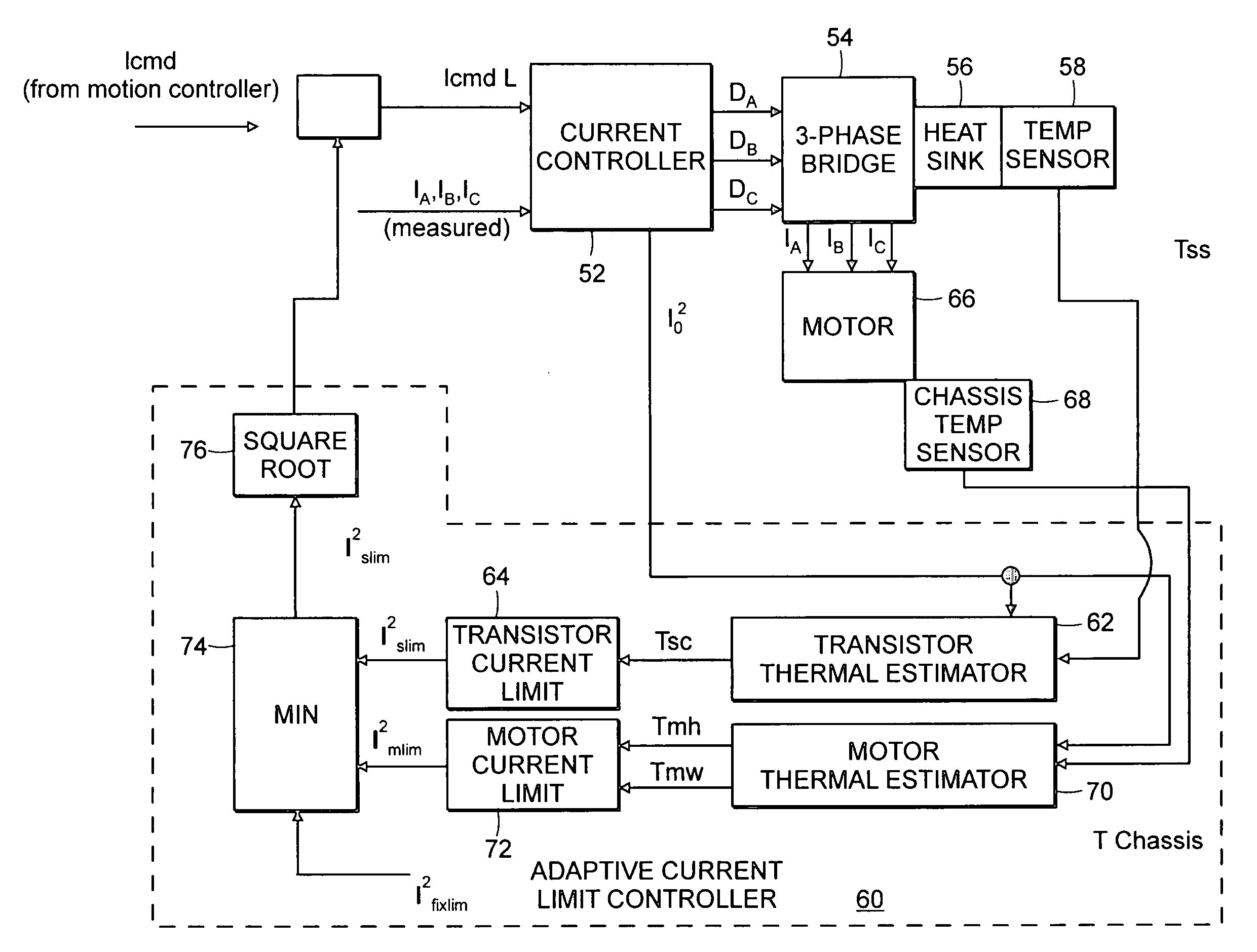
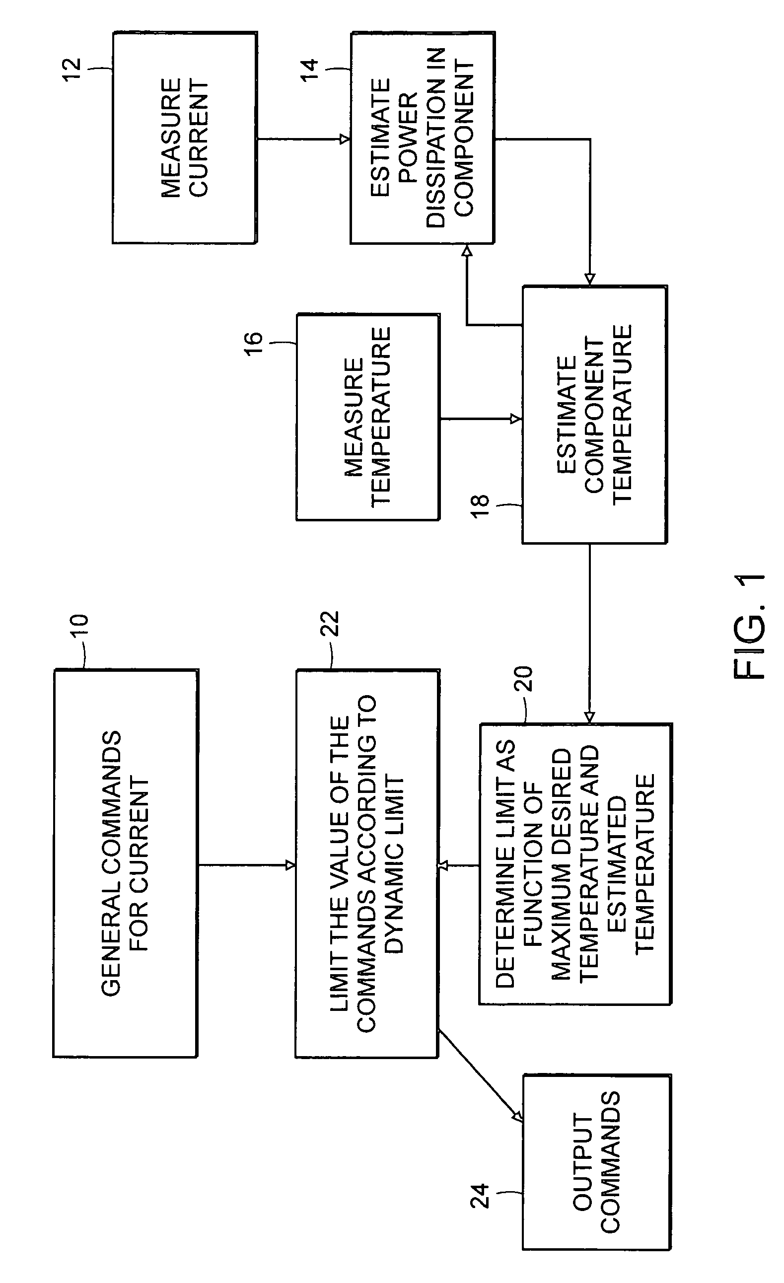
[0023]Referring to FIG. 1, a flow chart provides an overview of embodiments of methods of the present invention. Current commands may be generated 10 for and provided to any of a variety of components. In one particular embodiment, current commands are used for controlling a motor. A motion controller or speed control loop may be used in a known manner to generate current commands. The current commands regulate current through one or more power transistors which provide current to the motor windings. Any number of different devices may be operated by current commands in accordance with the present invention.
[0024]It is desirable to prevent the components from overheating and possibly failing as a result thereof. It is often difficult and expensive to obtain direct measurements of temperatures for the components of concern. Fortunately, a proxy for the temperature of the components of concern can be estimated. These estimates are used in accordance with embodiments of the invention t...
PUM
 Abstract
Description
Claims
Application Information