Arrangement for testing battery while under load and charging

a battery and charging arrangement technology, applied in secondary cell servicing/maintenance, instruments, electrochemical generators, etc., can solve problems such as system downtime, limited life times, and increased costs for ensuring reliable battery powered operation

Inactive Publication Date: 2006-01-31
LA MARCHE MFG
View PDF10 Cites 24 Cited by
  • Summary
  • Abstract
  • Description
  • Claims
  • Application Information

AI Technical Summary

Benefits of technology

[0009]A still further object of the present invention is to test the status of a battery, or plural connected batteries, and provide an indication to the battery user of either imminent failure of the battery or likely failure of the battery within a more extended period.

Problems solved by technology

Batteries age over time with use and thus have limited life times. In the case of rechargeable batteries, a charger is frequently connected to the battery to maintain the battery in a fully charged state.
This type of testing not only typically requires human intervention, but also frequently results in system downtime.
Disconnection of the battery from its associated load may require an alternative power source for temporary use or a separate backup power system, both of which increase the cost for ensuring reliable battery powered operation.
In addition, while current battery testers are capable of providing an indication of current battery status, they do not provide an indication of possible imminent battery failure such as due to sulfation.

Method used


Image

  • Arrangement for testing battery while under load and charging
  • Arrangement for testing battery while under load and charging
  • Arrangement for testing battery while under load and charging

Examples


Embodiment Construction

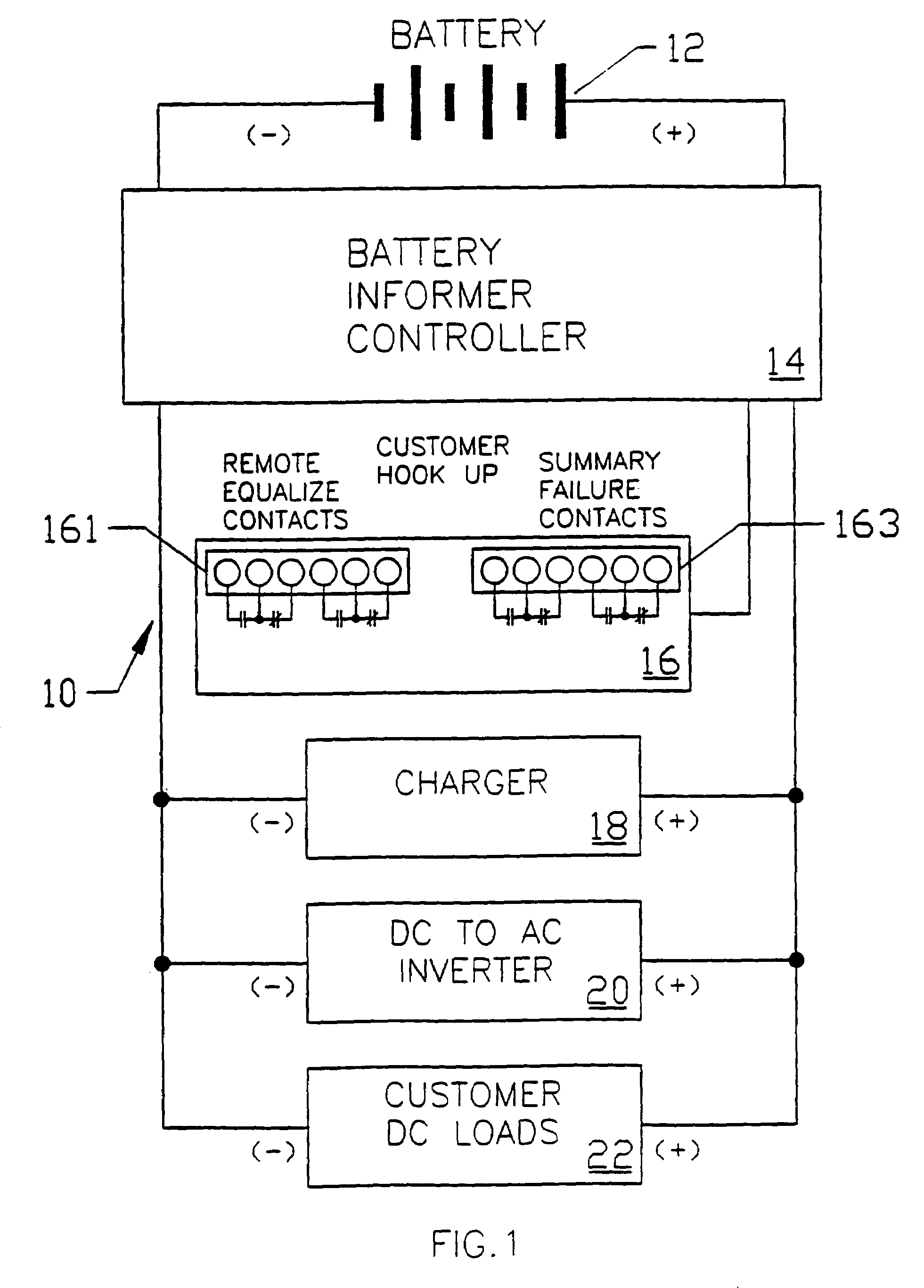
[0020]Referring to FIG. 1, there is shown a simplified block diagram of a live circuit battery tester 10 in accordance with the present invention. The live circuit battery tester 10 includes a battery informer controller 14 connected to a battery 12 for testing the status of the battery. The battery informer controller 14 includes a relay output circuit 16 having first TS1 terminals 161 and second TS2 terminals 163. A user of the live circuit battery tester 10 can connect appropriate instruments to the aforementioned TS1 and TS2 terminals 161, 163 for receiving various signals indicating the status of battery 12 as it is tested. A battery charger 18 can be connected across the terminals of the battery informer controller 14 for maintaining battery 12 in a charged state. During testing, the battery 12 may remain connected to one or more DC loads 22 via the battery informer controller 14. Similarly, a DC-to-AC inverter 20 may be connected across the terminals of the battery informer c...


PUM

PropertyMeasurementUnit
voltageaaaaaaaaaa
unidirectional conductoraaaaaaaaaa
time intervalsaaaaaaaaaa

Abstract

A live circuit battery tester allows for determining the condition of batteries under load without disconnecting the batteries and a battery charger from the load or in any way disrupting system operation during the test. Battery testing is prevented when the batteries are being used in an emergency or if they are recharging from a recent discharge. The battery tester is under microcomputer control and incorporates automatic-self diagnostics and provides a visual indication if the batteries are good or if a specific problem is detected such as if the batteries are missing, have open cells, are sulfated or are in imminent danger of failure. The battery tester determines if the charger is operating properly and tests for an open cell, bad battery connection, sulfated battery, and a weak battery and provides a visual indication of any of these problems as well as an indication of a properly operating battery.

Description

FIELD OF THE INVENTION[0001]This invention relates to apparatus for testing the status of a battery in virtually any system and is particularly directed to determining the condition of a battery (or batteries) without disconnecting the battery from the system while the battery is under load without disrupting system operation.BACKGROUND OF THE INVENTION[0002]Batteries used in the generation of electrical energy can take on various forms. Two of the most common forms of batteries in use today are the dry cell battery and the lead-acid storage battery. Dry cell batteries were named because the electrolyte is typically comprised of a non-spillable paste-like substance. Dry cell batteries find widespread usage in such items as flashlights, portable radios, hearing aids, and other electrical devices which are frequently carried about by a user. Lead-acid storage batteries are comprised of a lead dioxide, lead plates, and aqueous sulfuric acid all disposed within a sealed container.[0003]...

Claims


Application Information

Patent Timeline
Patent Type & Authority Patents(United States)
IPC IPC(8): G01N27/416
CPCG01R31/3631H01M10/48H01M10/425G01R31/3682H01M10/46G01R31/386G01R31/3646Y02E60/10
Inventor STEINKE, THOMAS O.
Owner LA MARCHE MFG
Why Eureka
Try Eureka