Electronic label reading system

Inactive Publication Date: 2006-01-31
TAGSYS
View PDF12 Cites 63 Cited by
  • Summary
  • Abstract
  • Description
  • Claims
  • Application Information

AI Technical Summary

Benefits of technology

[0011]The objectives of this invention are: to provide a possibly asynchronous solution for the item management problem; to cater for dynamic populations of labels; to provide for highly efficient and flexible multiple label reading protocols; to b

Problems solved by technology

In the case when no reply occurs, it is unproductive for the interrogator to continue to listen for a reply for longer that the time taken by the label to issue the precursor, and it is also unproductive for the interrogator to continue to receive a reply when collisions are occurring.
What we are catering for here is a repeated label programming failure, and we seem to have done all that is possible.
Obviously the interrogator will not want to get stuck in a cycle where two labels simultaneously are being programmed, and thus give colliding replies an end of the programming operation, which could cause

Method used


Image

  • Electronic label reading system
  • Electronic label reading system
  • Electronic label reading system

Examples


Embodiment Construction

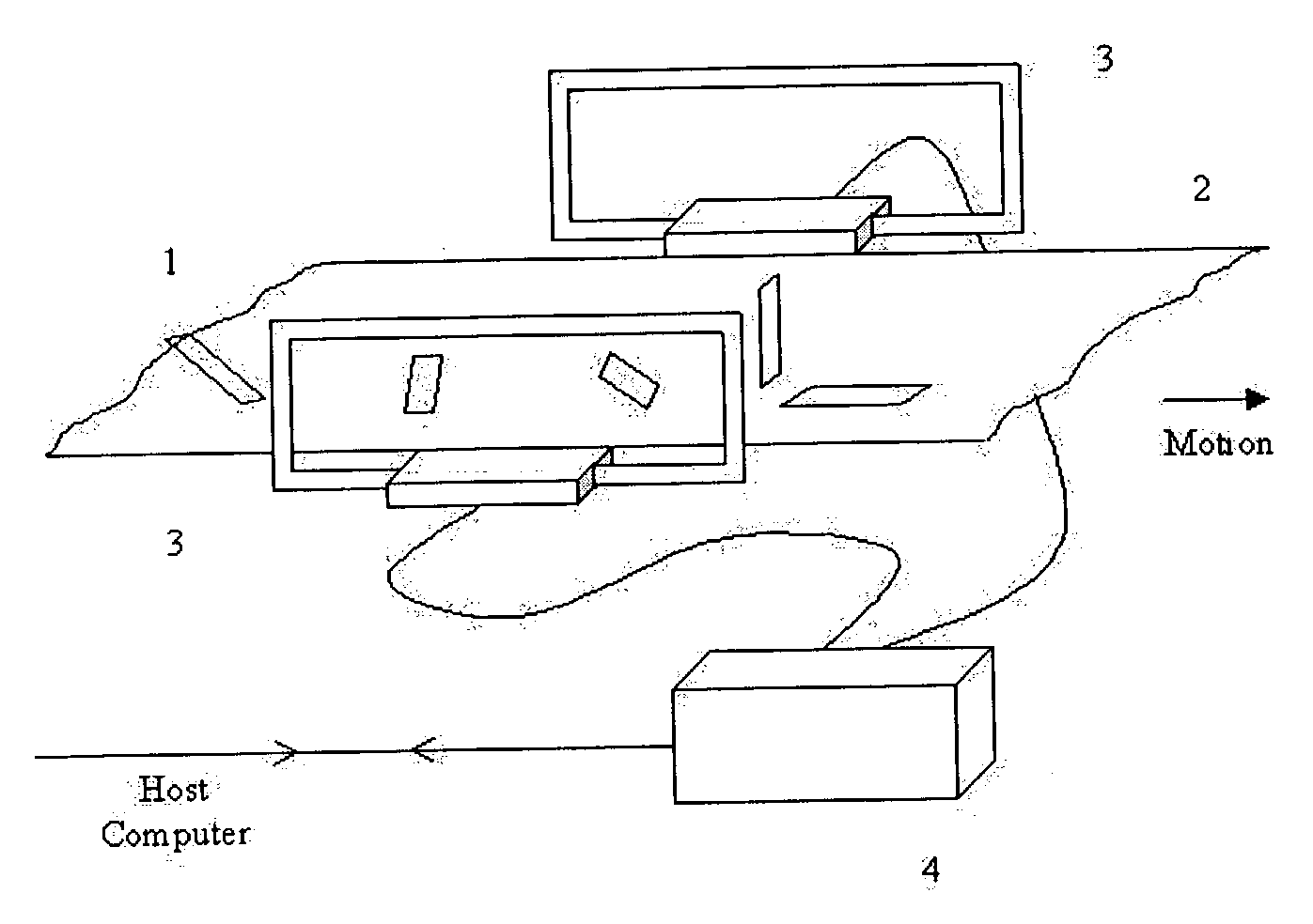
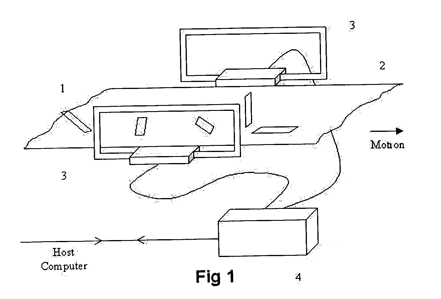
[0048]FIG. 1 shows in simplified form a preferred embodiment of the invention wherein a number of differently oriented electronic labels 1 are attached to objects, for convenience not shown, which are being transported on a conveyor 2 through an interrogation field region established between interrogation antennas 3 which are energised by a transmitter in interrogator 4 and return replies to a receiver therein. After the labels have been read, according to procedures to be described, information on the reading is passed over a data line to a host computer, not shown.

[0049]Notable in this structure is the fact that the labels are firstly at various distances from the interrogation antennas and secondly are variously oriented. Both of these factors will influence the degree of coupling to the generally magnetic interrogation field. Thirdly the labels are moving in and out of that field as the interrogation process proceeds.

[0050]As the labels enter the field they receive energising po...


PUM


Abstract

An electronic label reading system includes an interrogator including a transmitter and a receiver. The system also has a transmitter antenna connected to the transmitter for generating an interrogation electromagnetic field through which objects possessing code responding labels may pass. The code responding labels include label receiving antennas for receiving from the interrogation field a label interrogation signal, and generate label reply signals, and, from the label reply signals, reply electromagnetic fields. The system also has a receiver antenna connected to the receiver for receiving the reply signals from the label reply fields. The interrogation field and label reply fields provide a communication channel from the labels to the interrogator, and the interrogator signals to the labels condition information indicative of the condition of the communication channel.

Description

FIELD OF THE INVENTION[0001]The field of application of this invention lies in object management wherein information bearing electronically coded labels are attached to objects which are to be identified, sorted, controlled or audited by means of a process in which information passes between an interrogator, which creates an electromagnetic interrogation field, and electronically coded labels which respond by issuing a reply signal which is detected by the interrogator, decoded and supplied to other apparatus in the sorting, controlling or auditing process.BACKGROUND OF THE INVENTION[0002]Various instances of such systems are known, for example from Australian patent 658857 of Marsh and Lenarcic or Australian patent 664544 of Turner and Cole. In some variations of the system the interrogation medium may be other than electromagnetic, such as optic or acoustic.[0003]The present invention is related to and may include developments disclosed in applicant's PCT patent applications AU92 / ...

Claims


Application Information

Patent Timeline
IPC IPC(8): H04Q5/22G06K7/00G06K7/08G06K7/10
CPCG06K7/0008G06K7/10336G06K7/10435G06K7/10425G06K7/10346
Inventor COLE, PETER H.HALL, DAVID MALCOLMTURNER, LEIGH HOLBROOKKALINOWSKI, RICHARD
Owner TAGSYS
Why Eureka
Try Eureka