Transmit and receive system for cable data service

a technology of cable data and transmission system, applied in the field of data service, can solve the problems of system signal-to-noise ratio (snr) demands, current system might not be able to meet, etc., and achieve the effect of improving the peak ra

Active Publication Date: 2006-01-31
AT&T INTPROP II L P
View PDF5 Cites 17 Cited by
  • Summary
  • Abstract
  • Description
  • Claims
  • Application Information

AI Technical Summary

Benefits of technology

[0014]It has, in accordance with the present invention, been recognized that a third category of techniques exists which, in combination with protocols to be described hereinbelow, can be used to improve the peak rate. This category includes those techniques which utilize parallel transmission. Employing parallel transmission over conventional Data Over Cable Standard Interface Specification (DOCSIS) protocol channels has the advantage of allowing users of the DOCSIS protocol as well as users of the protocols described hereinbelow to simultaneously share the same channel. It has further been recognized in accordance with the present invention, that although a trade-off must be made between modem technology required for serial versus parallel transmission, comparisons between these two categories of technology reveal that the hardware for these two-types of modems will be similar at a future point in time. It has been further recognized that CATV network evolution, channel performance, and modem complexity should all play a role in choosing between the various approaches. From an IP networking perspective, it is simpler to provide a single “data link” below the IP layer. However, CATV evolution considerations favor the approach of transmitting the data over parallel RF channels.
[0015]Thus, in accordance with the present invention, a method of sending data from a transmit site to a receive site includes the steps of dividing a transmit data stream having a first bit rate into multiple data streams with each of the multiple data streams having a bit rate which is lower than the first bit rate, and transmitting each of the multiple data streams over a plurality of parallel RF channels wherein at least one of the RF channels serves a plurality of users. The method further includes the step of recombining the multiple data streams at the receive site to provide a receive data stream having a bit rate equal to the first bit rate. With this particular arrangement, a method that improves the peak data transmission rate from a headend to a subscriber is provided. The technique of the present invention improves the performance and efficiency of the network for transferring large files downstream by dividing the data and transmitting the data over parallel RF channels. Because the peak transmission rate of transmission control protocol / internet protocol (TCP / IP) in the downstream direction is affected by the performance of the upstream channel, and because additional upstream bandwidth may enable new services, the same principle can be applied to the upstream direction.
[0016]In accordance with a further aspect of the present invention, a system for sending data from a transmit site to a receive site includes a router, a tunnel source coupled to the router, and means for providing packets over multiple channels to a tunneling destination which receives the packets over the multiple channels and serializes the packets. With this particular arrangement, a system for enabling a data service which allows users to utilize a connection having a speed that is higher than the speed allowed by the current DOCSIS protocol is provided. The system of the present invention improves the performance and efficiency of the network for transferring large files downstream by dividing the data and transmitting the data in parallel over multiple channels. In a preferred embodiment, the channels are provided as multiple RF channels. Because the peak transmission rate of transmission control protocol / internet protocol (TCP / IP) in the downstream direction is affected by the performance of the upstream channel, and because additional upstream bandwidth may enable new services, same principle can be applied to the upstream direction.

Problems solved by technology

One problem with this category of solutions, however, is that this places strenuous demands on the system's signal-to-noise ratio (SNR), which current systems might not be able to meet.

Method used


Image

  • Transmit and receive system for cable data service
  • Transmit and receive system for cable data service
  • Transmit and receive system for cable data service

Examples


Embodiment Construction

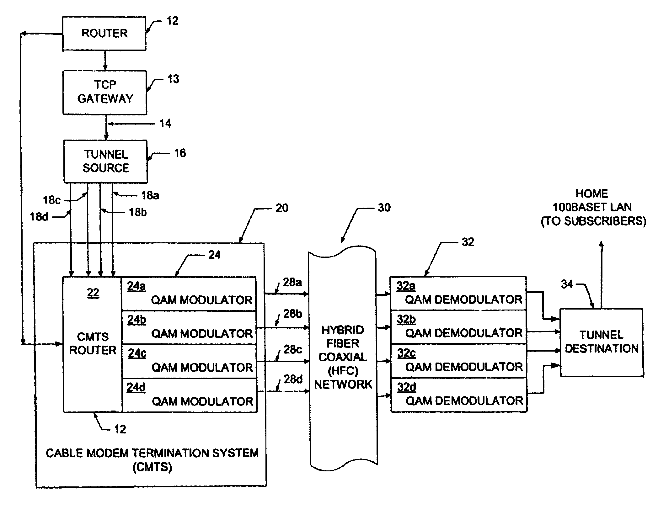
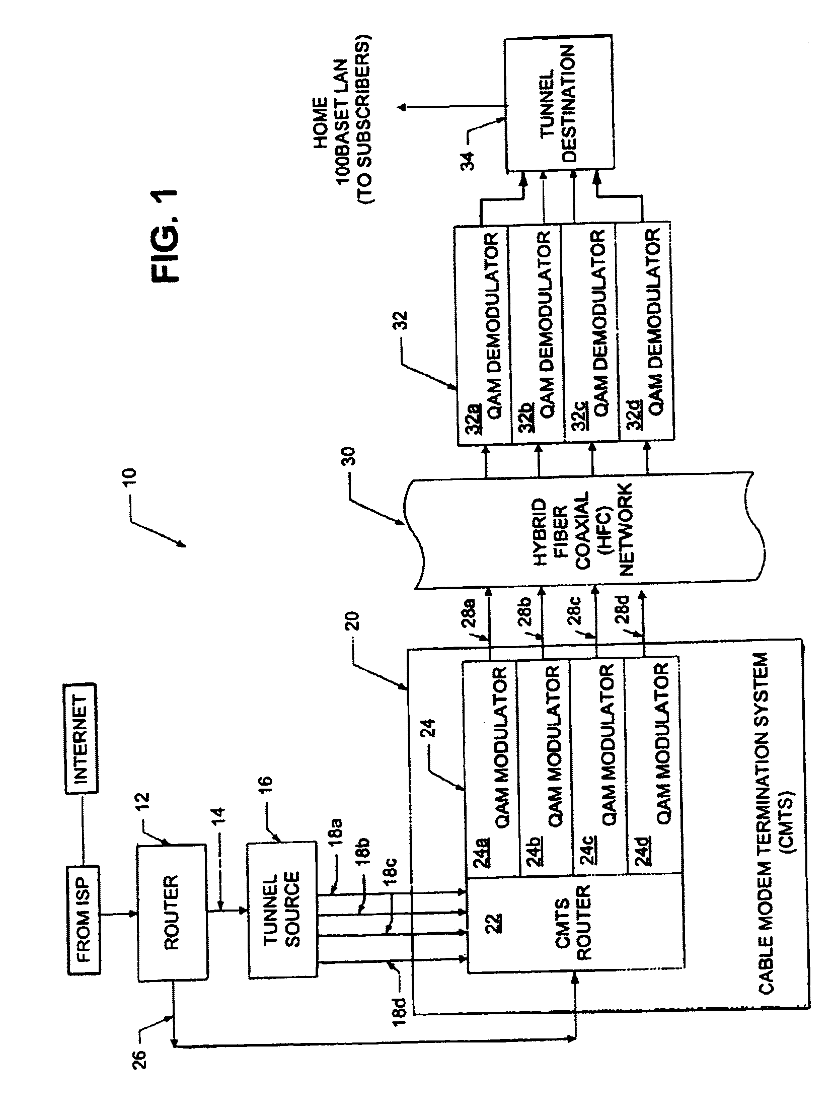
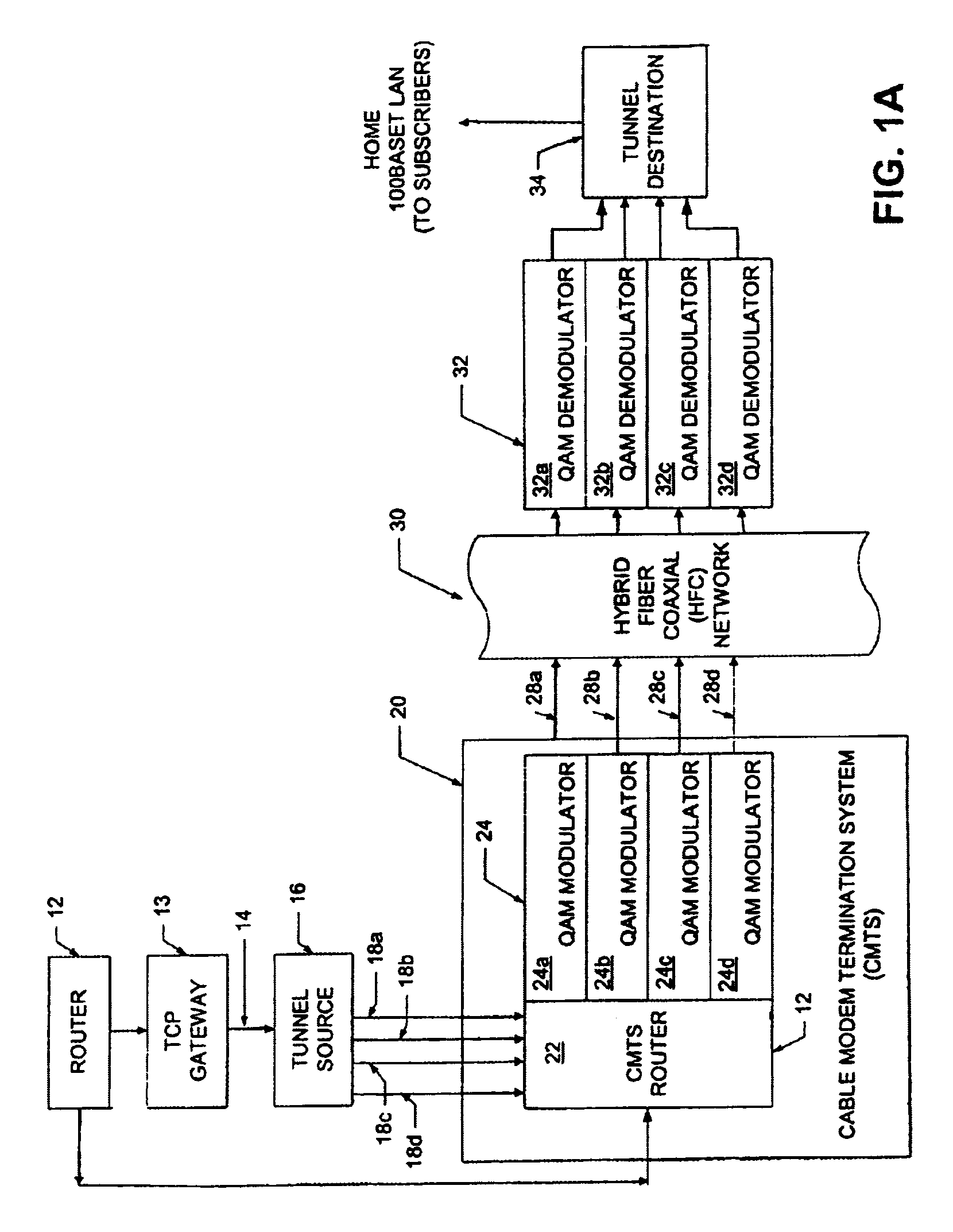
[0026]Referring now to FIG. 1, a downstream path of a transmission system 10 includes a first router 12 coupled to a tunnel source (also referred to as a sending tunnel end-point) 16 through a first signal path 14 (referred to hereinbelow as a FastChannel path). Tunnel source 16 is coupled to a cable modem termination system (CMTS) 20 through a second signal path 18 here shown as signal paths 18a–18d. It should be appreciated that the tunnel source 16 can functionally reside in a separate box upstream of the CMTS 20 as shown in FIG. 1. Alternatively, however, the tunnel source 16 can functionally reside within the CMTS 20 or the router 12. The CMTS 20 includes a CMTS router 22 and a plurality of quadrature amplitude modulators (QAMs) 24a–24d generally denoted 24. Router 12 is also coupled to the CMTS 20, and in particular to the CMTS router 22, via a signal path 26. The purpose of the signal paths 14 and 26 will next be described in general overview. In the system of the present inv...


PUM


Abstract

A transmit and receive system for transmitting data between a transmit site and a receive site. The system includes a tunnel source, router and modulator for dividing a transmit data stream having a first bit rate into multiple data streams with each of the multiple data streams having a bit rate which is lower than the first bit rate, transmitting each of the multiple data streams over a plurality of RF channels. The system further includes a demodulator and destination source for recombining the multiple data streams at the receive site to provide a receive data stream having a bit rate equal to the first bit rate.

Description

RELATED APPLICATIONS[0001]This application claims the benefit of U.S. Provisional Application No. 60 / 275,665 filed Mar. 14, 2001 which application is hereby incorporated herein by reference in its entirety.GOVERNMENT RIGHTS[0002]Not Applicable.FIELD OF THE INVENTION[0003]This invention relates generally to a data service and related apparatus and more particularly to a cable data service and system.BACKGROUND OF THE INVENTION[0004]As is known in the art, in addition to the transmission of television signals, it has been recognized that a cable network can also be used to transmit other types of data between remote locations. Thus, the cable network of the cable industry may be used as an alternative to communicating data via conventional telephone networks, such as the public switched telephone network (PSTN) for example.[0005]In this regard, cable networks are currently being used to transmit data to and from subscribers located at remote locations. Each subscriber location include...

Claims


Application Information

Patent Timeline
Patent Type & Authority Patents(United States)
IPC IPC(8): H04J3/04H04L12/28H04L25/14H04L29/06
CPCH04L12/2801H04L12/2856H04L12/2861H04L25/14H04L29/06H04L12/2898H04L69/14H04L9/40
Inventor DESAI, BHAVESH N.SHANKARANARAYANAN, NEMMARA K.SHUR, DAVID HILTONSMILJANIC, ALEKSANDRATOTLAND, TODD J.VAN DER MERWE, JACOBUS E.WOODWARD, SHERYL LEIGH
Owner AT&T INTPROP II L P
Why Eureka
Try Eureka