Apparatus and methods for tuning antenna impedance using transmitter and receiver parameters

a technology of antenna impedance and transmitter, applied in the field of wireless communication apparatus and methods, can solve the problems of association loss of power in the transferred signal, impedance mismatch, and possible causes of impedance mismatch, so as to and reduce the presented impedance difference

Inactive Publication Date: 2006-01-31
SONY ERICSSON MOBILE COMM AB
View PDF19 Cites 177 Cited by
  • Summary
  • Abstract
  • Description
  • Claims
  • Application Information

AI Technical Summary

Benefits of technology

[0008]In some embodiments, the signal parameter is indicative of an amount of power reflected in the received signal. The controller may reduce the presented impedance difference between the antenna and the receiver when the reflected power does not satisfy a threshold value and / or reduce the presented impedance difference between the transmitter and the antenna when the reflected power satisfies the threshold value.
[0009]In other embodiments, the signal parameter is indicative of a received signal strength of the received signal. The controller may reduce the presented impedance difference between the antenna and the receiver when the received signal strength does not satisfy a threshold value and / or reduce the presented impedance difference between transmitter and antenna when the received signal strength satisfies a threshold value.
[0010]In other embodiments, the signal parameter is indicative of a bit error rate of the received signal. The controller may reduce the presented impedance difference between the antenna and the receiver when the bit error rate does not satisfy a threshold value and / or reduce the presented impedance difference between transmitter and antenna when the bit error rate satisfies a below value.
[0011]In other embodiments, the signal parameter is indicative of when the receiver is actively receiving signals and / or the transmitter is actively transmitting signals. The controller may reduce the presented impedance difference between the antenna and the receiver when the receiver is active and / or reduce the presented impedance difference between transmitter and antenna when the transmitter is active.
[0012]In this manner, the impedance transformation circuit may adjust the impedances in response to one or more static or time-varying parameters associated with received signals and / or transmitted signals. Further, the performance of the transmitter or receiver may be selectively improved as will be described in the following detailed description.

Problems solved by technology

Impedance mismatches between the transmitter and the antenna or between the antenna and receiver can cause reflection of transmitted signals or received signals, respectively, and an associated loss of power in the transferred signals.
During use, however, the impedances of the antenna, transmitter, and receiver may change, resulting in impedance mismatches.
Impedance mismatches may be caused, for example, by motion of the communications apparatus and / or the presence of reflective or shielding objects in its operating environment.
When impedances are matched for one frequency band, they can become mismatched during operation in other frequency bands.
Such a mismatch can become particularly apparent for communications apparatus that operate in multiple frequency bands, such as those provided for Global System for Mobile Communication (GSM), Digital Communications System (DCS), Advanced Mobile Phone Services (AMPS), Personal Communication Services (PCS), or wireless local area network (WLAN).
For such apparatus, impedance mismatch may cause unacceptable power loss in signals transmitted or received as the apparatus operates between transmit and receive frequency ranges and between frequency bands.

Method used


Image

  • Apparatus and methods for tuning antenna impedance using transmitter and receiver parameters
  • Apparatus and methods for tuning antenna impedance using transmitter and receiver parameters
  • Apparatus and methods for tuning antenna impedance using transmitter and receiver parameters

Examples


Embodiment Construction

[0017]The present invention will now be described more fully with reference to the accompanying drawings, in which typical embodiments of the invention are shown. This invention may, however, be embodied in many different forms and should not be construed as limited to the embodiments set forth herein; rather, these embodiments are provided so that this disclosure will be thorough and complete, and will fully convey the scope of the invention to those skilled in the art. Like numbers refer to like elements throughout.

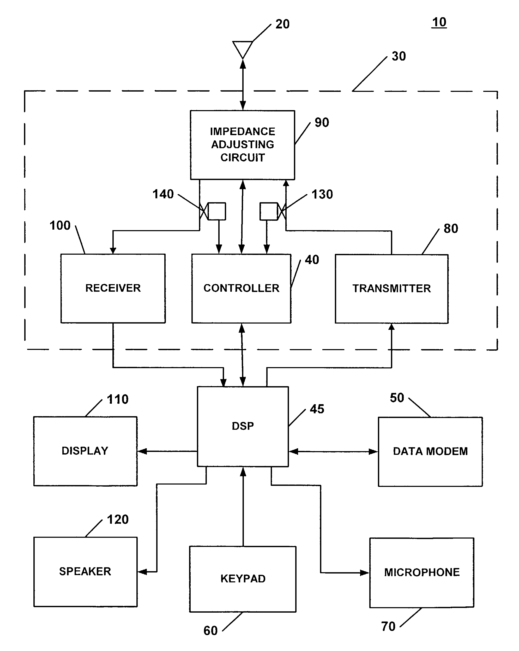
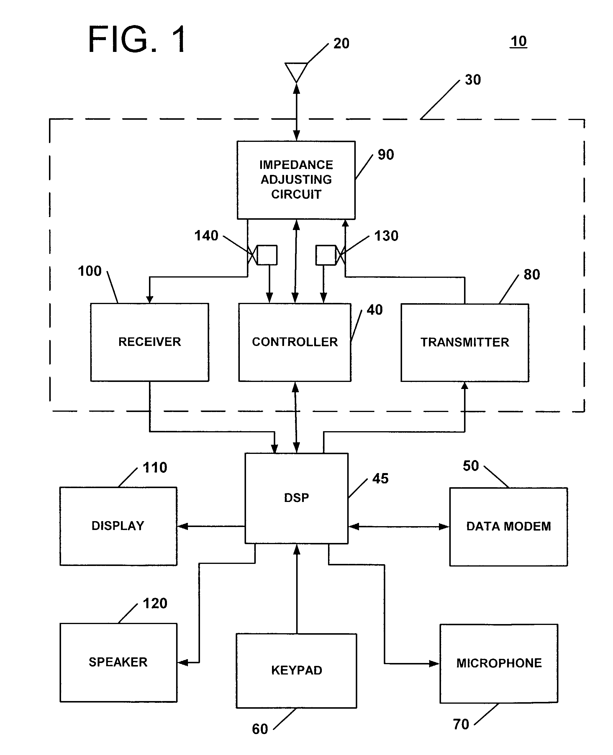
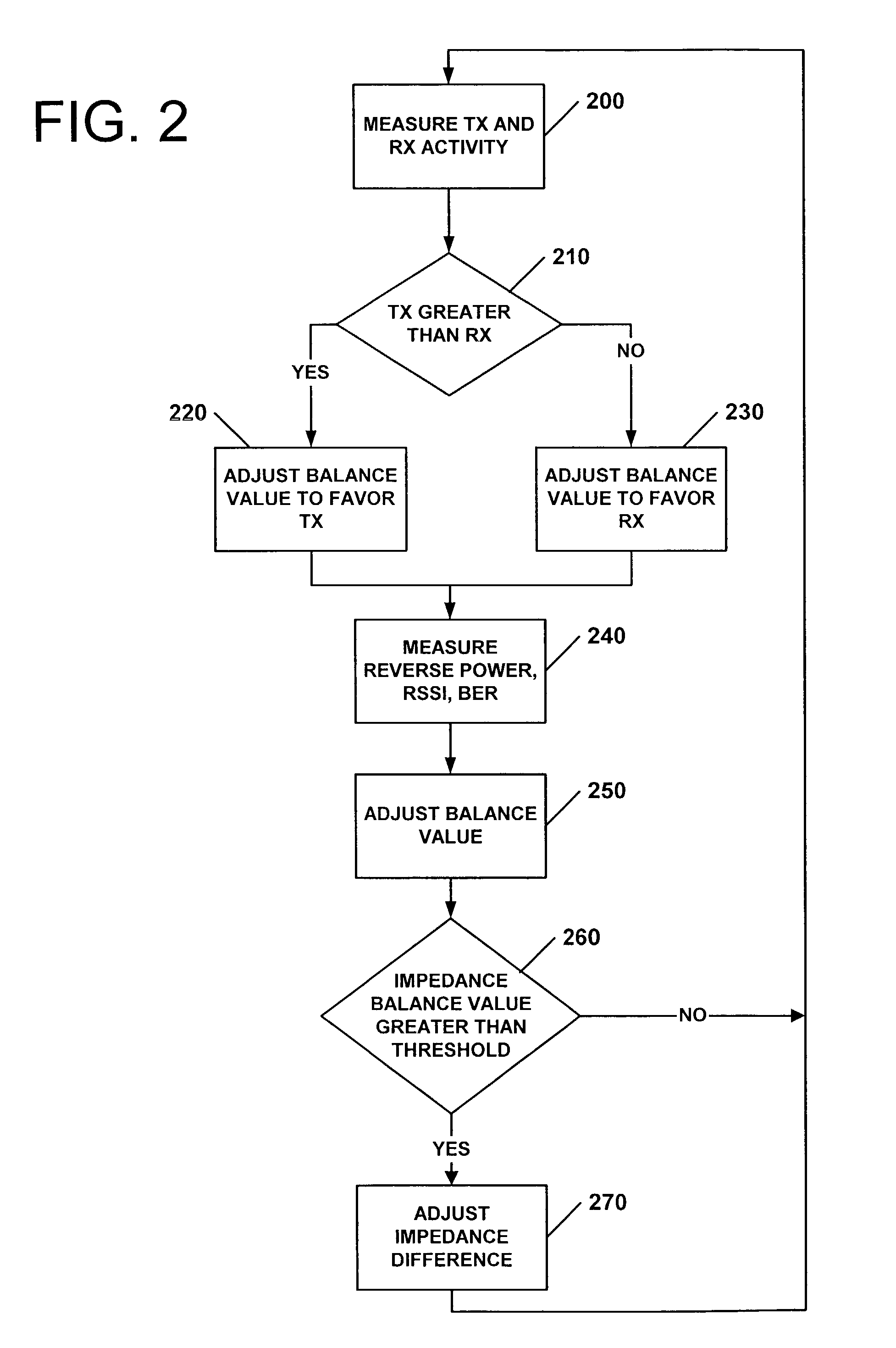
[0018]According to some embodiments of the present invention, impedance transformation circuits and methods may be provided. FIGS. 1–4 illustrate exemplary apparatus and methods according to embodiments of the present invention. It will be understood that operations depicted in the figures, and combinations thereof, may be implemented using one or more electronic circuits. It will also be appreciated that, in general, operations depicted in the diagrams, and combination...


PUM


Abstract

According to some embodiments of the present invention, an impedance transformation circuit is provided for use with a transmitter, a receiver, and an antenna. The transmitter may provide transmission signals for transmission by the antenna. The antenna may provide received signals having an associated signal parameter to the receiver. The impedance transformation circuit includes an impedance adjusting circuit and a controller. The impedance adjusting circuit is connected between the antenna, the receiver, and the transmitter. The impedance adjusting circuit is configured to change an impedance difference presented between at least one of: 1) the transmitter and the antenna, and 2) the antenna and the receiver, in response to a control signal. The controller generates the control signal to change the presented impedance difference in response to a signal parameter.

Description

FIELD OF THE INVENTION[0001]The present invention relates generally to wireless communication apparatus and methods, and more particularly to adjusting the impedance presented to a transmitter, receiver, and antenna in a wireless communication apparatus.BACKGROUND OF THE INVENTION[0002]Wireless communications apparatus often include a transmitter, a receiver, and an antenna. Information signals can be encoded and amplified by the transmitter and transferred to the antenna for radiation to the environment. Information signals received by the antenna can be transferred to the receiver where they can be decoded and amplified. Impedance mismatches between the transmitter and the antenna or between the antenna and receiver can cause reflection of transmitted signals or received signals, respectively, and an associated loss of power in the transferred signals. Efficient power transfer of transmission signals can occur when the impedance presented between the transmitter and the antenna ar...

Claims


Application Information

Patent Timeline
Patent Type & Authority Patents(United States)
IPC IPC(8): H04B1/46H03H7/40H04B1/04H04B1/18
CPCH04B1/18H04B1/0458H03H7/40H03F2200/504
Inventor SMITH, JR., EDWARD LEE
Owner SONY ERICSSON MOBILE COMM AB
Why Eureka
Try Eureka