Method and system for monitoring problem resolution of a machine

a technology for monitoring and problem resolution, applied in the field of machine diagnostics and repair, can solve the problems of difficult to precisely identify a failed component the effect or problems of failure on the system or subsystem are often neither readily apparent nor resolved, and the difficulty of precisely identifying the failure condition or other cause of failure conditions

Inactive Publication Date: 2006-01-31
GENERAL ELECTRIC CO
View PDF80 Cites 42 Cited by
  • Summary
  • Abstract
  • Description
  • Claims
  • Application Information

AI Technical Summary

Problems solved by technology

Considering the complexity of locomotive systems and subsystems it is sometimes difficult to precisely identify a failed component or other cause of the failure conditions.
This may be because the effects or problems that the failure has on the system or subsystem are often neither readily apparent in terms of their source nor unique.
Sometimes the recommended fix for a problem may not resolve the problem due to the complexity of the problem and / or diagnostic efforts.
However, with more complex problems, conducting a diagnosis and recommending a proper fix may be more difficult.
An improper diagnosis and / or recommended fix instruction may lead to the inefficient operation or underutilization of a locomotive or fleet of locomotives.
This is turn may cause an economic loss to the locomotive or fleet operator, which the operator would rather avoid.
However, more complex equipment and process diagnostics seldom have such simple correspondences.
Consequently, recommended fix instructions may be made that do not solve a problem immediately or completely.
Not determining expeditiously that an executed fix instruction did not work may lead to recommending the same improper fix when that problem is next identified.

Method used


Image

  • Method and system for monitoring problem resolution of a machine
  • Method and system for monitoring problem resolution of a machine
  • Method and system for monitoring problem resolution of a machine

Examples


Embodiment Construction

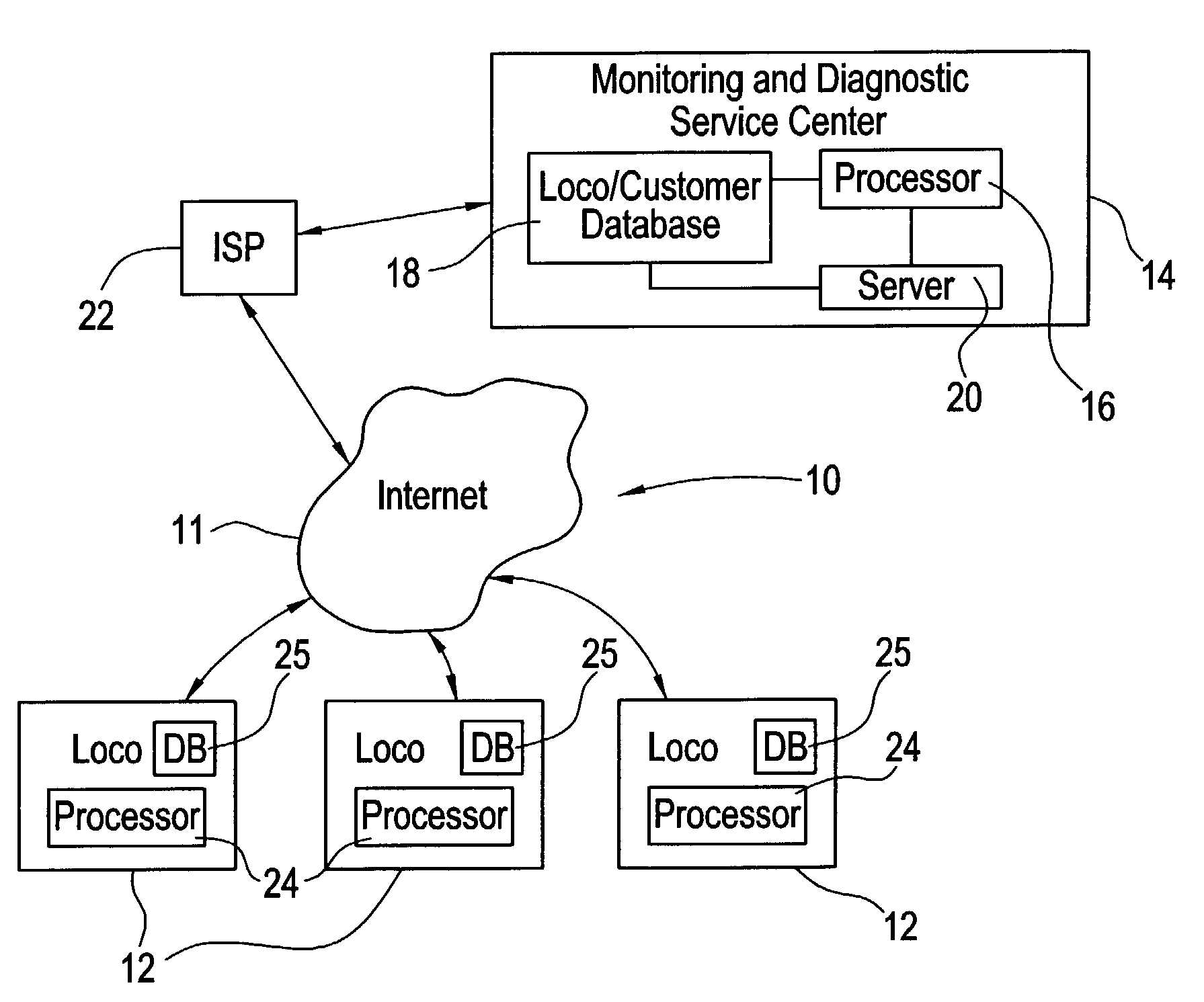
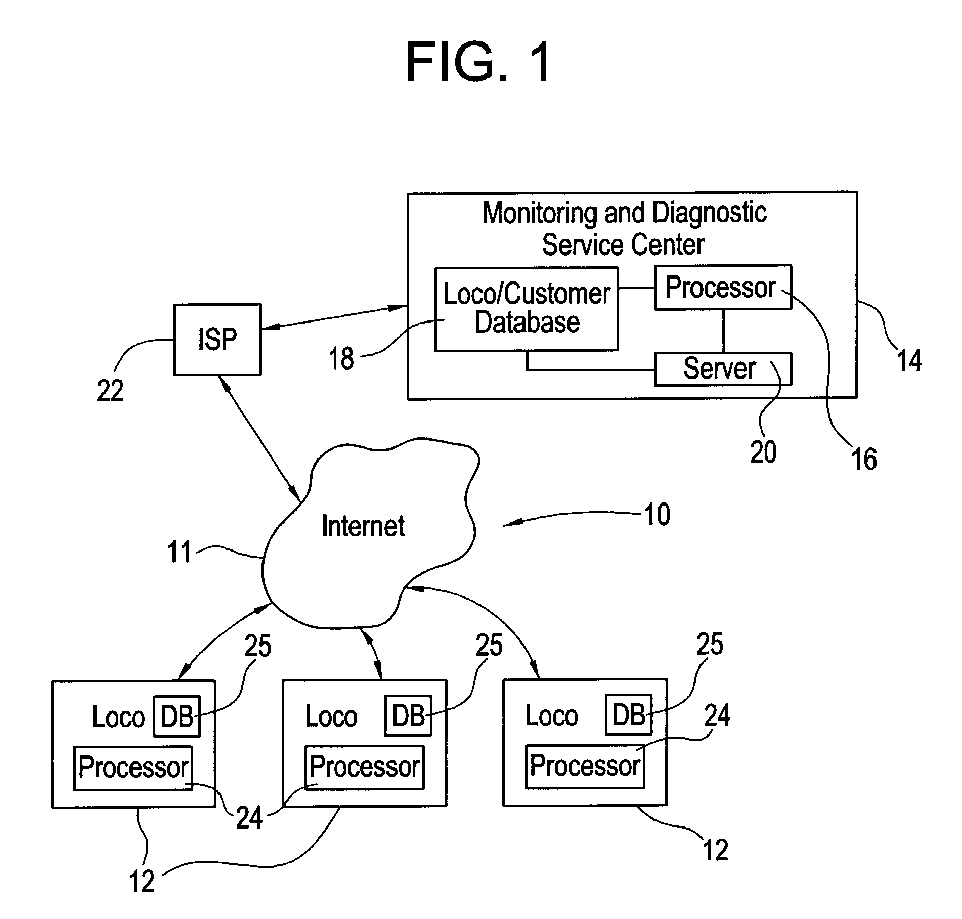
[0010]FIG. 1 illustrates an exemplary telecommunications system 10 that may be used to implement at least one aspect of the present invention. The telecommunications system 10 may include using the Internet 11 for a wireless or hard wire connection between a plurality of mobile or fixed assets and a centralized control and / or service center 14. In one exemplary embodiment of the present invention each asset may be a vehicle used for transportation such as a locomotive 12, for example, and the centralized control center 14 may be a monitoring and diagnostic service center (“MDSC”) such as one managed and operated by the assignee of the present invention. The control center 14 may be remotely located from the locomotives 12 and may include conventional computer processing components such as a processor 16, a Loco / Customer database 18 and a server 20. The processor 16 may include a variety of processing modules capable of executing computer-readable code for implementing aspects of the...


PUM


Abstract

A method and apparatus for determining when to close a problem case associated with a machine that includes identifying at least one failure condition associated with the problem case, determining whether the failure condition is repeated after a recommended fix instruction is executed and closing the problem case if the failure condition does not repeat within a predetermined amount of time after the fix instruction has been executed. The machine may be a remote machine such as a locomotive and electronic data indicative of the failure condition may be transmitted from the remote machine to a control center over a telecommunications medium such as the Internet. The control center may include a processor for managing the electronic data that may be transmitted from a plurality of remote machines. The control center processor may be adapted to request downloads from the remote machines and monitor downloaded data to determine whether the failure condition are repeating after the fix instruction has been executed.

Description

BACKGROUND OF THE INVENTION[0001]This invention generally relates to machine diagnostics and repair and more particularly to a method and system for monitoring the resolution of malfunctions or breakdowns of machines, such as locomotives, once a diagnosis has been given to ensure that the malfunction or breakdown is properly repaired.[0002]A locomotive is one example of a complex electromechanical system comprising a plurality of complex systems and subsystems. Many if not all of these systems and subsystems are manufactured from components that will fail over time. The operational parameters of a locomotive system or subsystem are frequently monitored during operation of the locomotive to detect potential failures. If a failure condition or a set of failure conditions is detected then a service technician may conduct a diagnostics examination of the failure conditions and make a recommendation for fixing the problem. Considering the complexity of locomotive systems and subsystems i...

Claims


Application Information

Patent Timeline
Patent Type & Authority Patents(United States)
IPC IPC(8): G06F11/00B61L27/00G06F11/07G06F11/273
CPCB61L27/0094G06F11/0748G06F11/2294G06F11/0793G06F11/079B61L27/57
Inventor RODDY, NICHOLAS EDWARDGIBSON, DAVID RICHARDBLILEY, RICHARD GERALD
Owner GENERAL ELECTRIC CO
Why Eureka
Try Eureka