
Gas turbine plant

a technology of gas turbines and plants, applied in the field of gas turbine plants, can solve the problems of increasing the power per unit flow of combustion gas, difficult to greatly improve the flow characteristic and reduce mechanical loss, and exhausted fossil fuel resources, so as to reduce the flow rate of fuel, improve the heat efficiency of the plant, and eliminate defects.

Inactive Publication Date: 2006-02-07
KK TOSHIBA
View PDF10 Cites 22 Cited by
  • Summary
  • Abstract
  • Description
  • Claims
  • Application Information

AI Technical Summary

Benefits of technology

[0013]A primary object of the present invention is to substantially eliminate defects or drawbacks encountered in the prior art described above and to provide a gas turbine plant capable of relatively reducing a flow rate of fuel so as to improve a plant heat efficiency without giving any influence to other constituent equipments when using the gas turbine plant itself as a heating source for heating a fuel.
[0215]According to the present invention of the various aspects mentioned above, in the gas turbine plant according to the present invention, the high pressure air of the air compressor is used as a heating source for heating a fuel supplied from the fuel section to the gas turbine combustor. Further, the gas turbine plant is provided with means for cooling the high temperature sections of the gas turbine by reusing the high pressure air which has been used for heating the fuel. Therefore, the quantity of heat (energy) of fuel increases while the plant heat efficiency being improved, and it is possible to sufficiently deal with the high output accompanying with the high temperature gas turbine drive gas supplied to the gas turbine.
[0216]Further, in the gas turbine plant according to the present invention, in the case where the high pressure air from the air compressor is used as a heating source so as to heat the fuel, there is provided a heat exchange section, and the heat exchange section is provided with safety means. Therefore, the gas turbine plant can be safely operated without giving any hindrance to other components.
[0217]Further, in the gas turbine plant according to the present invention, in the case where the high pressure air which has been used for heating the fuel is reused as a cooling medium for cooling the gas turbine high temperature section, there is provided a pressure rising compressor, and the pressure rising compressor includes means capable of taking sufficient measures if an accident happens in the pressure rising compressor. Therefore, it is possible to securely cool the high temperature section of the gas turbine, and to keep the material strength of the high temperature section at a preferable state.

Problems solved by technology

In view of the gas turbine output power in the light of the improvement of the plant heat efficiency, there is a problem of an increase in a power per unit combustion gas flow (specific power).
However, an improvement of flow characteristic of a gas turbine blade and a reduction in other mechanical loss have already reached the limit, and it is difficult to greatly improve the flow characteristic and reduce the mechanical loss.
As described above, in the Japanese Patent No. 2540646, efforts have been made to reduce fuel consumption and to improve a plant heat efficiency because there is an anxiety that fossil fuel resources are exhausted in near future.
However, the heated water on the outlet side of the economizer 6 has been used as a heating source of the fuel F, and for this reason, there have arisen several problems.
Thus, a feed water pump 6a requires a high pressure rising force, and thus, this is a factor of increasing the cost.
As a result, there is the possibility that steaming is generated.
For example, in the case of a simple cycle gas turbine, it is difficult to secure a heating source, and for this reason, there has been required a gas turbine plant which can readily secure the heating source.
As described above, the prior art shown in FIG. 29 can improve the plant heat efficiency, but provides the aforesaid several problems.

Method used


Image

  • Gas turbine plant
  • Gas turbine plant
  • Gas turbine plant

Examples


first embodiment

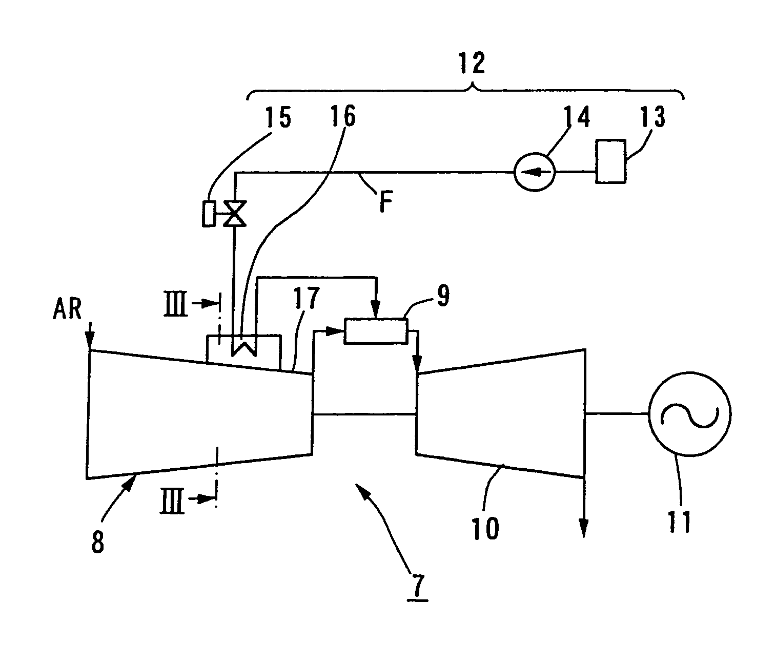
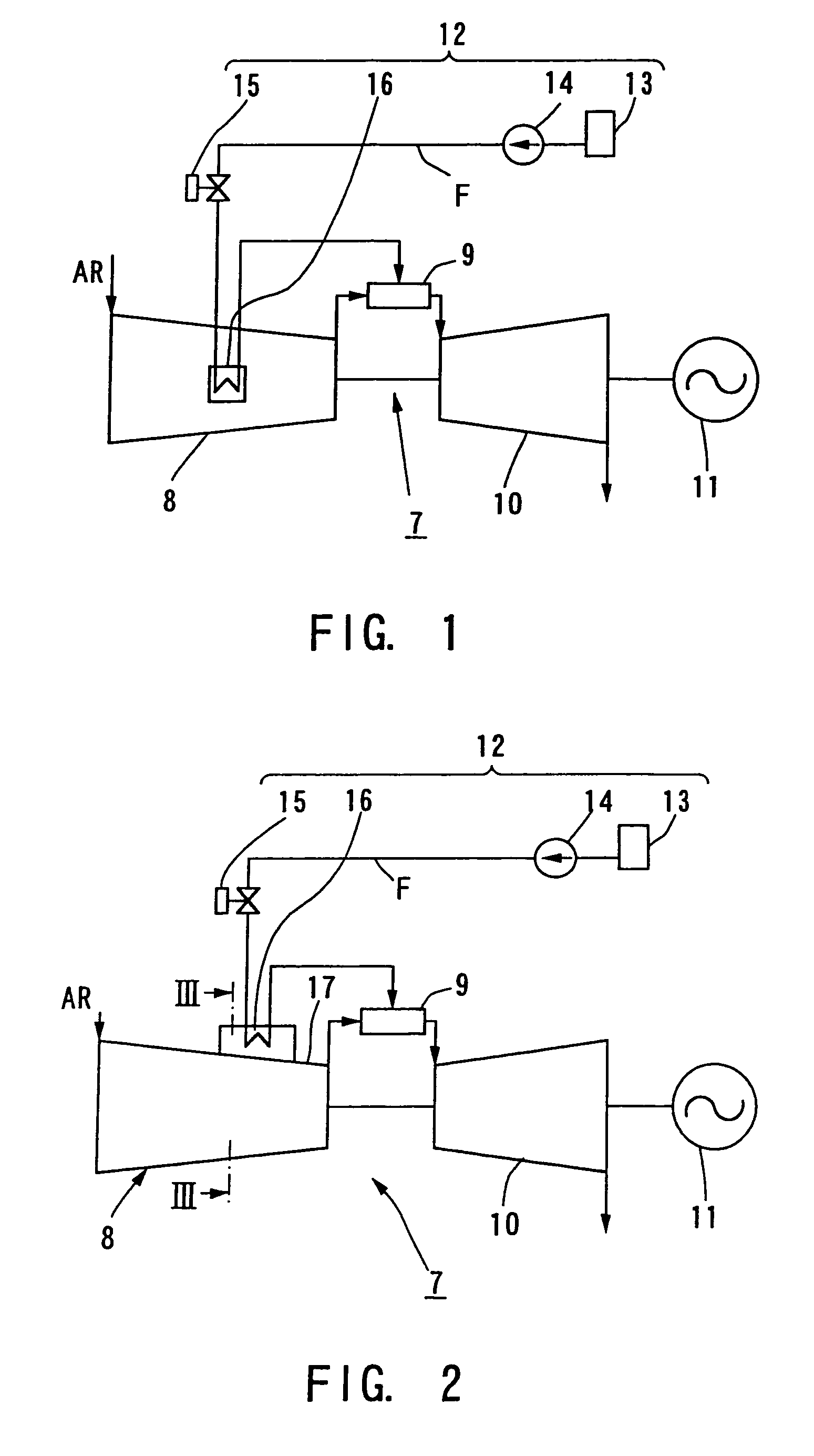
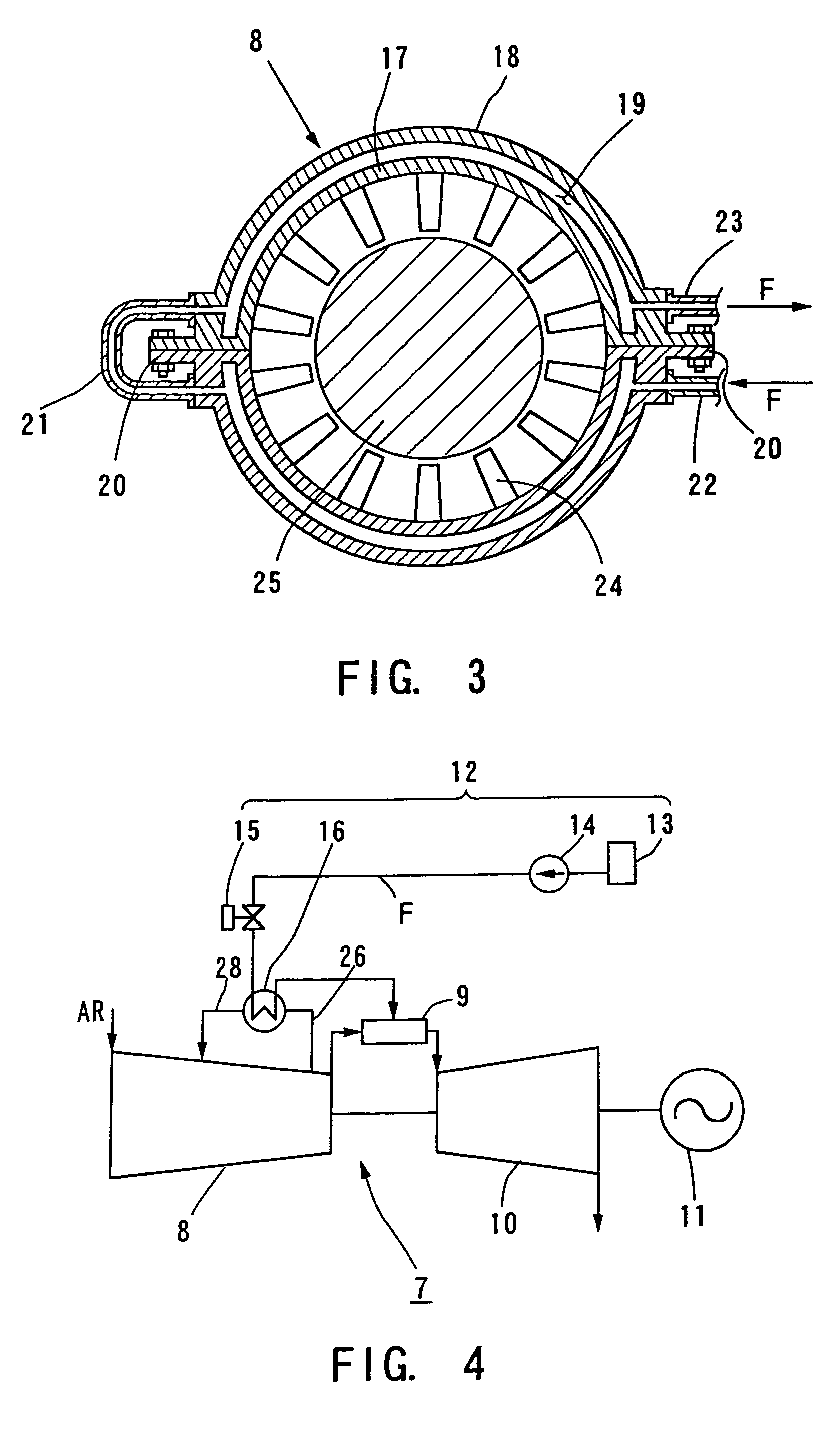
[0250]FIG. 1 is a system diagram schematically showing a gas turbine plant according to the present invention.

[0251]A gas turbine plant 7 includes an air compressor 8, a gas turbine combustor 9, a gas turbine 10, a driven equipment 11 such as a generator, and a fuel section 12.

[0252]In the gas turbine plant 7, an air AR sucked in the air compressor 8 is made high in pressure, and the high pressure air (highly pressurized air) is supplied to the gas turbine combustor 9 together with a fuel F from the fuel section 12. A gas turbine driving combustion gas (main flow gas) generated by the gas turbine combustor 9 is supplied to the gas turbine 10, and then, the gas turbine combustion gas is expanded so as to rotate and drive the driven equipment 11 with a rotating torque generated in the expanding process.

[0253]On the other hand, the fuel section 12 includes a fuel tank 13, a fuel pump 14, and a fuel valve 15, and in this structure, the fuel section 12 may be called a fuel supply section...

fourth embodiment

[0286]In this embodiment, these supply systems 29a and 29b are provided with the pressure rising compressors 33a and 33b, respectively. Thus, like the fifth modified embodiment of the fourth embodiment, the fuel F is heated by the heat exchange section 16 of the fuel section 12, and it is possible to securely supply the high pressure air whose temperature becomes low to the high temperature sections 31a and 31b. Therefore, it is possible to sufficiently meet with the gas turbine 10 of the gas turbine plant 7 heated to a high temperature.

[0287]FIG. 13 is a system diagram schematically showing a seventh modified embodiment of the gas turbine plant according to the fourth embodiment of the present invention. In this case, like reference numerals are used to designate the same components as the fourth embodiment or the corresponding part.

[0288]In this embodiment, the following matter is taken into consideration. Specifically, a pressure loss in the high pressure air passing through the ...

eighth embodiment

[0305]In this eighth embodiment, the following matter is taken into consideration. More specifically, when the high pressure air extracted from the air compressor 8 is used as a heating source and the fuel F is heated in the heat exchange section 16 of the fuel section 12, in the case where the fuel F leaks into the high pressure air, this is a factor of causing an accident. For this reason, the heat exchange section 16 is provided with a fuel leak detector 45, a valve opening control section 46, an alarm device 47 and a fuel leak display device (indicator) 48.

[0306]The valve opening control section 46 is constructed so as to close a fuel valve 15 if a fuel leak signal detected by the fuel leak detector 45 exceeds a predetermined value. The alarm device 47 also gives the alarm if a fuel leak signal detected by the fuel leak detector 45 exceeds a predetermined value. The fuel leak display 48 displays a leaked fuel concentration detected by the fuel leak detector 45 so that a worker c...


PUM


Abstract

A gas turbine plant comprises an air compressor, gas turbine including at least one high temperature section, a driven equipment, which are operatively connected in series, a gas turbine combustor arranged between the air compressor and the gas turbine, a fuel system disposed for supplying a fuel to the gas turbine combustor, and a heat exchange section for heating the fuel from the fuel by means of a high pressure air as a heating medium fed from the air compressor.

Description

BACKGROUND OF THE INVENTION[0001]The present invention relates to a gas turbine plant, and in particular, to a gas turbine plant which previously heats a fuel supplied to a gas turbine combustor of the gas turbine plant and enhances a quantity of heat so as to improve a plant heat (thermal) efficiency.[0002]In a gas turbine plant, it has been known that the plant heat efficiency is improves if an inlet combustion temperature of a gas turbine is made high. The plant heat efficiency is calculated from a ratio of a gas turbine power to a fuel supplied to a gas turbine combustor.[0003]Therefore, how to reduce a fuel to be supplied to the gas turbine combustor, or how to enhance an output of the gas turbine is an important matter in order to improve the plant heat efficiency.[0004]In view of the gas turbine output power in the light of the improvement of the plant heat efficiency, there is a problem of an increase in a power per unit combustion gas flow (specific power). However, an impr...

Claims


Application Information

Patent Timeline
Patent Type & Authority Patents(United States)
IPC IPC(8): F02C7/224F02C6/18F02C7/18
CPCF02C7/12F02C7/185F02C7/224Y02E20/16Y02E20/14F05D2260/205F02C6/18F02C7/18
Inventor KOBAYASHI, TADASHIOKAMURA, TAKANARIITO, SHOKOUSASAKI, TAKASHIKOGA, AKINORI
Owner KK TOSHIBA
Learn More