Thermal control systems for process tools requiring operation over wide temperature ranges

a technology of temperature control system and process tool, applied in the direction of refrigeration system, compression machine with cascade operation, lighting and heating apparatus, etc., can solve the problems of inability to meet the wide temperature range economically by conventional refrigeration system, inability to meet the requirements of space, efficiency and reliability, and specific refrigerant further imposes some inherent limitations, so as to improve the useful life and increase the reliability

Active Publication Date: 2006-02-07
BE AEROSPACE INCORPORATED
View PDF10 Cites 15 Cited by
  • Summary
  • Abstract
  • Description
  • Claims
  • Application Information

AI Technical Summary

Benefits of technology

[0009]A number of features are included in these modules to improve useful life, increase reliability and provide assurances against catastrophic failures. The refrigerant unit in the second refrigeration unit presents theoretical problems because of gas pressure buildup, due to the low boiling point, but this is obviated by the use of an excess gas chamber as well as a preset pressure burst disks. The thermal transfer loop is substantially confined within the second lower stage module, but nonetheless includes a storage reservoir, a differential pressure regulation system, and a gas purge system.

Problems solved by technology

For such applications, long life and high reliability are essential, but the requirements also include compactness and small footprint because of the high costs of floor footage in such facilities.
It should be intuitively evident that such a wide temperature range cannot be met economically by conventional refrigeration systems.
The use of a number of refrigeration units (four in the Mizuno et al proposal) presents particular problems in terms of space requirements, efficiency and reliability.
Any specific refrigerant further imposes some inherent limitation, depending upon its critical temperature, on the range of operation.
In addition efficiency is inherently reduced when heating must be employed to counteract over-cooling.

Method used


Image

  • Thermal control systems for process tools requiring operation over wide temperature ranges
  • Thermal control systems for process tools requiring operation over wide temperature ranges
  • Thermal control systems for process tools requiring operation over wide temperature ranges

Examples


Embodiment Construction

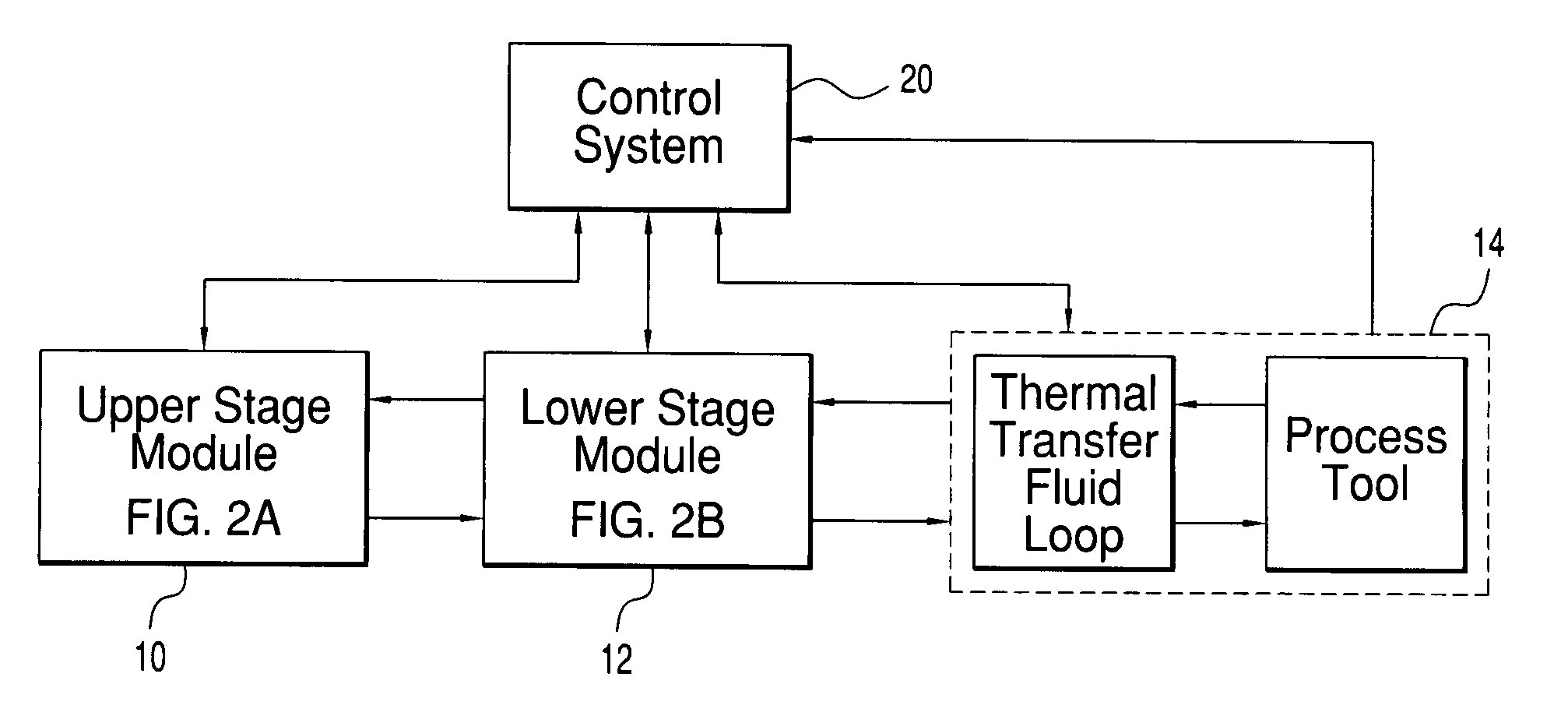
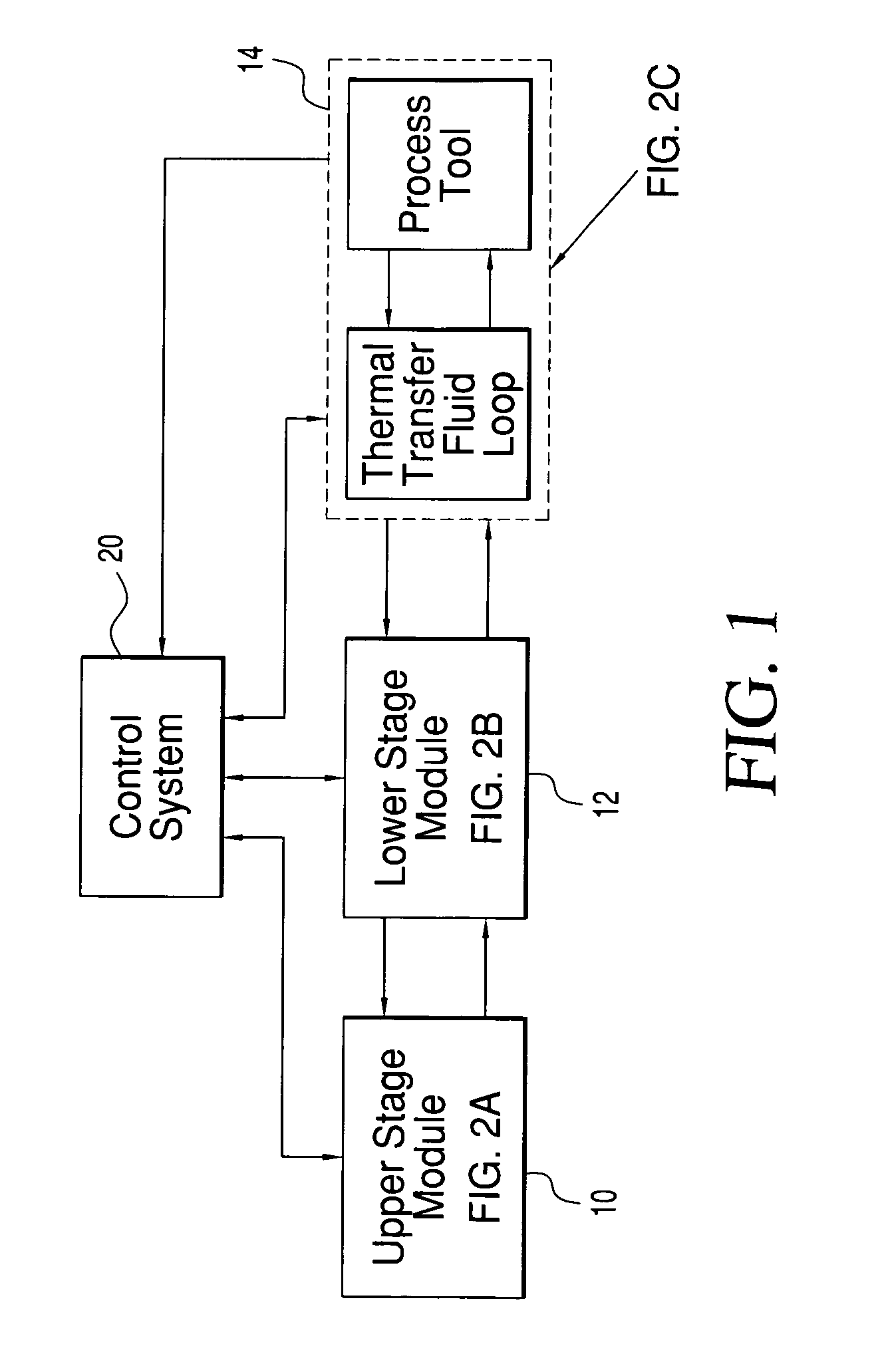
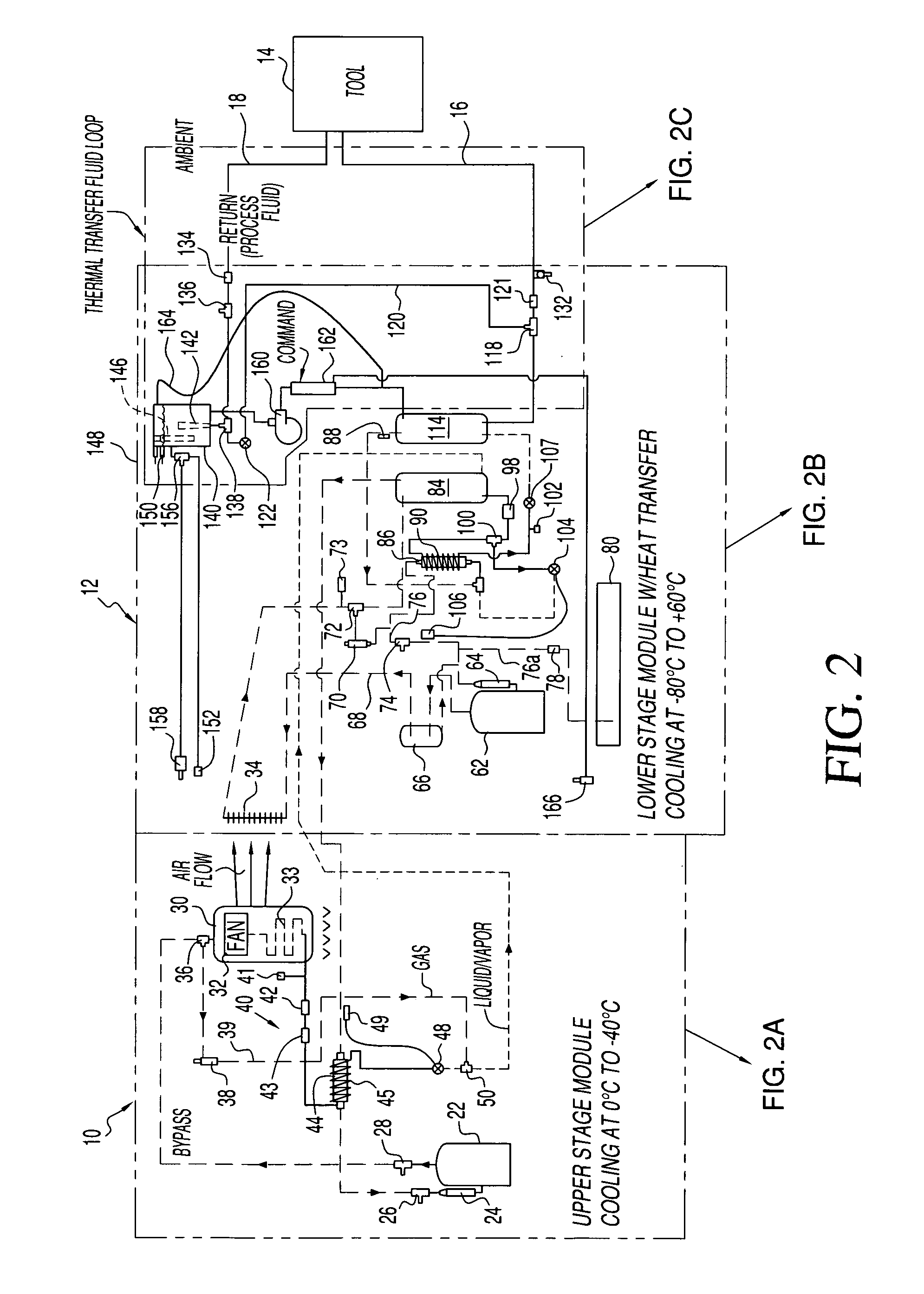
[0017]Systems and methods in accordance with the invention are founded on the apparatus shown in FIGS. 1 and 2, to which reference is now made. The primary units are, as seen in FIG. 1, an upper (temperature) stage module 10 using a first refrigerant, and a lower (temperature) stage module 12 employing a different refrigerant and interchanging thermal energy with the upper stage module 10 in various ways. The lower stage module 12 exchanges thermal energy, at a final temperature level that is at, above or below ambient, with a thermal transfer fluid that feeds through a process tool 14 in a loop, via a supply line 16 and a return line 18. Because of the number of individual units that are employed in the stages, details are depicted in added Figures by subdividing some principal elements of FIG. 1 into the composite system of FIG. 2, then providing diagrams which delineate details of the two modules (upper and lower stage, respectively), as separate FIGS. 2A and 2B and the final the...


PUM


Abstract

A system and method for maintaining the temperature of a thermal transfer fluid at a selectable level within a wide temperature range, so as to operate a process tool in a chosen mode employing at least two cascaded stages, each operating with a different fluid in a separate refrigeration cycle. By interrelating energy transfers between parts of upper and lower stages, thermal efficiency is maximized and a smooth continuum of temperature levels can be provided. The refrigerants advantageously have vaporization points below and above ambient, for upper and lower stages respectively, and employs the upper stage for a constant refrigeration capacity, controlling the final temperature with the lower stage. The system allows for a further extension of range because the thermal transfer fluid can be heated for some process tool modes as the refrigeration cycles are run at low loads.

Description

FIELD OF THE INVENTION[0001]This invention relates to temperature control systems which heat and / or cool separate process equipment by circulating thermal transfer fluid at a temperature which may be selected within a wide range but precisely maintained.BACKGROUND OF THE INVENTION[0002]Applicant has previously developed temperature control units utilizing pressurized liquid refrigerant, expansion valve devices, and heat exchangers / evaporators to provide the thermal capacity needed for cooling or heating thermal transfer fluid that flows within a process tool, in order to maintain the tool at a selected temperature level. The units function with high thermal efficiency, provide precise control, and meet the demanding needs of modern high-capital intensive industries, such as semiconductor industries using cluster tools. For such applications, long life and high reliability are essential, but the requirements also include compactness and small footprint because of the high costs of fl...

Claims


Application Information

Patent Timeline
Patent Type & Authority Patents(United States)
IPC IPC(8): F25B7/00
CPCF25B7/00F25B25/005F25B2400/01F25B40/04F25B40/00
Inventor COWANS, KENNETH W.
Owner BE AEROSPACE INCORPORATED
Why Eureka
Try Eureka