Fluid processing device and method

a technology of processing device and flue gas, which is applied in the direction of hydrogen/synthetic gas production, chemical production, bulk chemical production, etc., can solve the problems of limited cost of operation and/or construction of such units, and achieve the effect of reducing the cost of operation and/or construction

Active Publication Date: 2006-02-07
BATTELLE MEMORIAL INST
View PDF26 Cites 37 Cited by
  • Summary
  • Abstract
  • Description
  • Claims
  • Application Information

AI Technical Summary

Problems solved by technology

However limitations are often encountered regarding the cost of operation and / or construction of such units.

Method used


Image

  • Fluid processing device and method
  • Fluid processing device and method
  • Fluid processing device and method

Examples


example 1

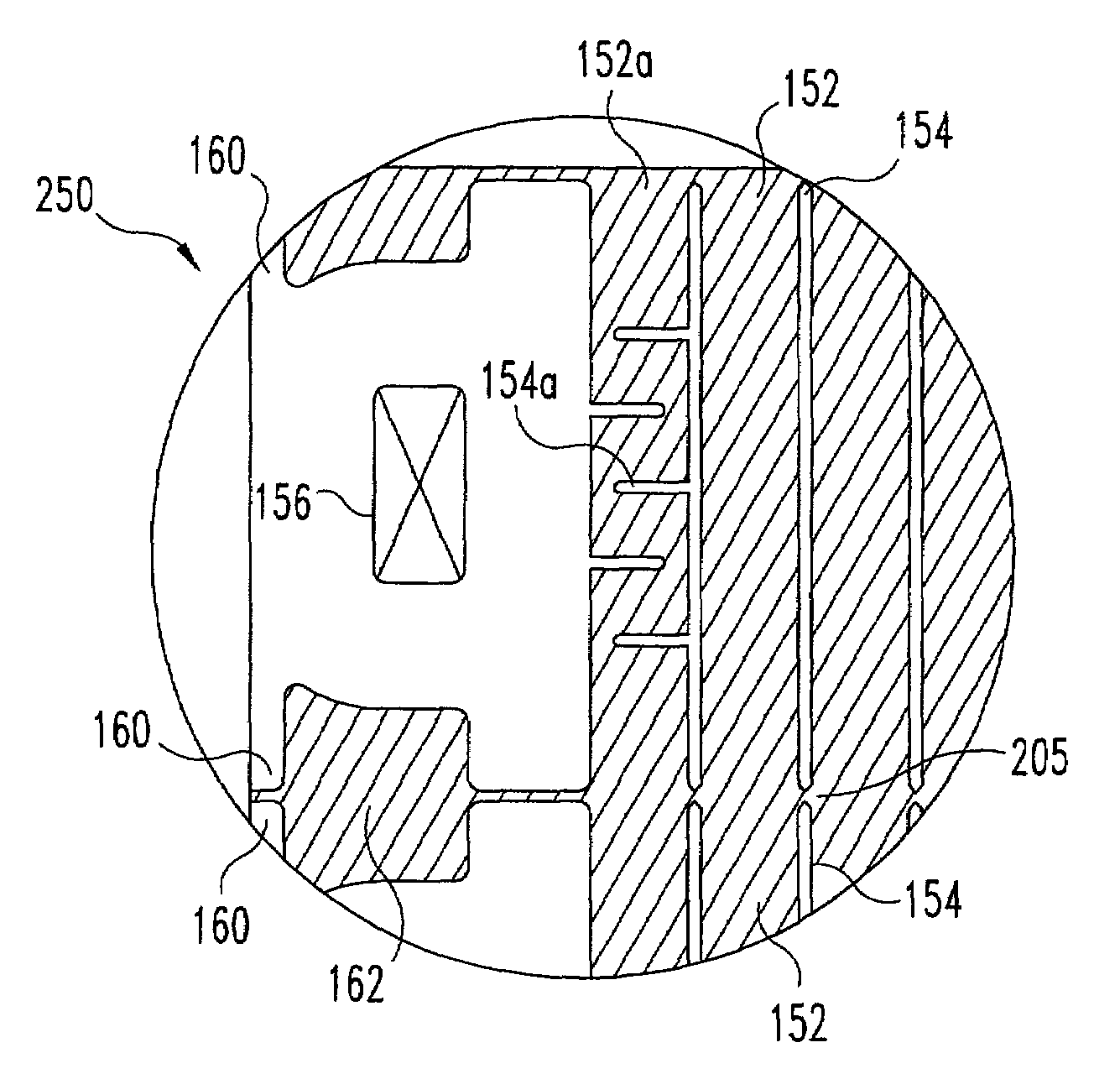
[0066]A water vaporizer was constructed according to the shim design illustrated in FIGS. 4 and 5 with 121 pairs of shim 250 alternately stacked with 120 of shim 270. All shims were formed of stainless steel and were 4.4 inches long (full length, from tab 160 to tab 160) and 0.5 inches wide. The combustion side shims were 0.0155 inches thick with steam channels etches 0.01 inches deep. The steam side shims were 0.01 inches thick with the steam / water channel etched 0.005 inches deep. After diffusion bonding, the stainless steel endplates were machined to a thickness of 0.1 inches and the vaporizer was installed in the assembly of FIG. 1.

[0067]Heat transfer of 10 Watts per cubic centimeter (W / cm3) based on total panel volume was obtained while vaporizing water inlet at ambient temperature (approx. 20° C.) to steam outlet at ambient pressure. The combustion gas was inlet at 500° C. and a flow rate of about 900 standard liters per minute (slpm). The combustion gas pressure drop was 2.5 ...

example 2

[0068]Using the device of Example 1 at 1 cubic centimeter per second of water feed at ambient temperature, 900 slpm inlet combustion gas at 480° C., open discharge, and a gas side pressure drop of less than 2.5 inches of water, the steam outlet temperature was about 425° C.

example 3

[0069]Using the device of Example 1 it is expected that about 80 W / cm3 of heat transfer based on total panel volume can be obtained with a 40 inch of water pressure drop for water vaporization with a combustion gas.


PUM

PropertyMeasurementUnit
Reynolds numberaaaaaaaaaa
depthaaaaaaaaaa
depthaaaaaaaaaa

Abstract

A fluid processing unit having first and second interleaved flow paths in a cross flow configuration is disclosed. The first flow paths are substantially longer than the second flow paths such that the pressure drop in the second flow paths can be maintained at a relatively low level and temperature variations across the second flow paths are reduced. One or more of the flow paths can be microchannels. When used as a vaporizer and / or superheater, the longer first flow paths include an upstream liquid flow portion and a downstream vapor flow portion of enlarged cross sectional area. A substantial pressure drop is maintained through the upstream liquid flow portion for which one or more tortuous flow channels can be utilized. The unit is a thin panel, having a width substantially less its length or height, and is manufactured together with other thin units in a bonded stack of thin metal sheets. The individual units are then separated from the stack after bonding.

Description

RELATED APPLICATION DATA[0001]This application claims the benefit of U.S. Provisional Application Ser. No. 60 / 296,295 filed Jun. 6, 2001, and U.S. Provisional Application Ser. No. 60 / 363,269 filed Mar. 11, 2002 the disclosures of which are hereby incorporated by reference. GOVERNMENT RIGHTS[0002]This invention was made with Government support under Contract Number DE-AC06-76RLO 1830 awarded by the U.S. Department of Energy. The Government has certain rights in the invention.INTRODUCTION[0003]The present invention is directed to a fluid processing unit and method of manufacture. More particularly, but not exclusively, the present invention is directed to a low pressure drop microchannel heat exchanger and a method of manufacture.[0004]Light weight, small-scale, fluid processing units have been developed for a variety of applications, including military, automotive, and remote location uses to name just a few. However limitations are often encountered regarding the cost of operation a...

Claims


Application Information

Patent Timeline
Patent Type & Authority Patents(United States)
IPC IPC(8): B01D53/54F26B7/00B81B1/00B01B1/00B01J19/00B01J35/04C01B3/16C01B3/38C01B3/58C01C1/04F28D9/00F28F3/08
CPCB01B1/005B01J35/04C01B3/16C01B3/384C01B3/583C01B3/586C01C1/0417C01C1/0452F28D9/0043F28D9/0093B01J19/0093F28F2275/061B01J2219/00162B01J2219/00783B01J2219/00835B01J2219/00873C01B2203/0205C01B2203/0283C01B2203/044C01B2203/0445C01B2203/047C01B2203/0844C01B2203/0883F28D2021/0064F28F2260/02F28F2210/02Y02P20/52
Inventor WHYATT, GREG A.DAVIS, JAMES M.
Owner BATTELLE MEMORIAL INST
Why Eureka
Try Eureka