Thermographic wiring inspection
- Summary
- Abstract
- Description
- Claims
- Application Information
AI Technical Summary
Benefits of technology
Problems solved by technology
Method used
Image


Examples
Embodiment Construction
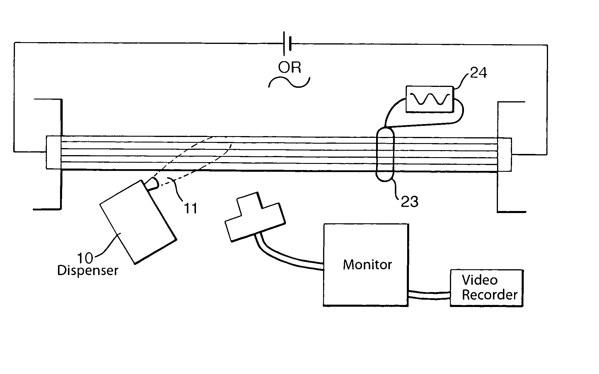
[0037]FIG. 1a shows a loom 1, comprising several cables 2, which form part of the avionics system of an aircraft (not shown). The loom 1 is connected to form part of an electrical circuit 3 for allowing either alternating or direct current to flow through the cables 2. An infra-red thermal imaging system 4 is shown, which comprises an infra-red thermal imaging camera 5, a display monitor 6 and a video recorder 7. The camera 5 is connected to the display monitor 6 by cables 8. The monitor 6 is for displaying the thermal images detected by the camera 5 and these images may then be recorded by the video recorder 7, which is connected to the monitor 6 by cables 9.
[0038]In operation, the loom is connected to an electrical circuit which is then switched on. As current flows through the loom 1, heat is dissipated by the cables 2 and this is detected by the camera 5 and displayed on the monitor 6 as a thermal image. The camera 5 is slowly moved along the loom 1 so as to detect the intensity...
PUM
 Abstract
Description
Claims
Application Information
 - Generate Ideas
- Intellectual Property
- Life Sciences
- Materials
- Tech Scout
- Unparalleled Data Quality
- Higher Quality Content
- 60% Fewer Hallucinations
Browse by: Latest US Patents, China's latest patents, Technical Efficacy Thesaurus, Application Domain, Technology Topic, Popular Technical Reports.
© 2025 PatSnap. All rights reserved.Legal|Privacy policy|Modern Slavery Act Transparency Statement|Sitemap|About US| Contact US: help@patsnap.com