

Fuse barrier and power circuit employing the same
a technology of fuse barrier and power circuit, which is applied in the direction of protective switch, electrical apparatus, protective switch operating/releasing mechanism, etc., can solve the problems of carbon and metallic dust over all components enclosed by fuse, insufficient time, and extensive damage to protective barriers, so as to reduce the dispersion of vaporized materials and molten parts.
- Summary
- Abstract
- Description
- Claims
- Application Information
AI Technical Summary
Benefits of technology
Problems solved by technology
Method used
Image

Examples
Embodiment Construction
[0026]As employed herein, the statement that two or more parts are “connected” or “coupled” together shall mean that the parts are joined together either directly or joined through one or more intermediate parts. Further, as employed herein, the statement that two or more parts are “attached” shall mean that the parts are joined together directly.
[0027]As employed herein, the term “fastener” shall expressly include, but not be limited to, any suitable fastening member(s) (e.g., without limitation, a threaded fastener; a non-threaded fastener; a removable fastener; a non-removable fastener; a bolt; a machine screw; a rivet; a soldered connection; an adhesive connection), which is employed such that two or more parts are connected or coupled together.
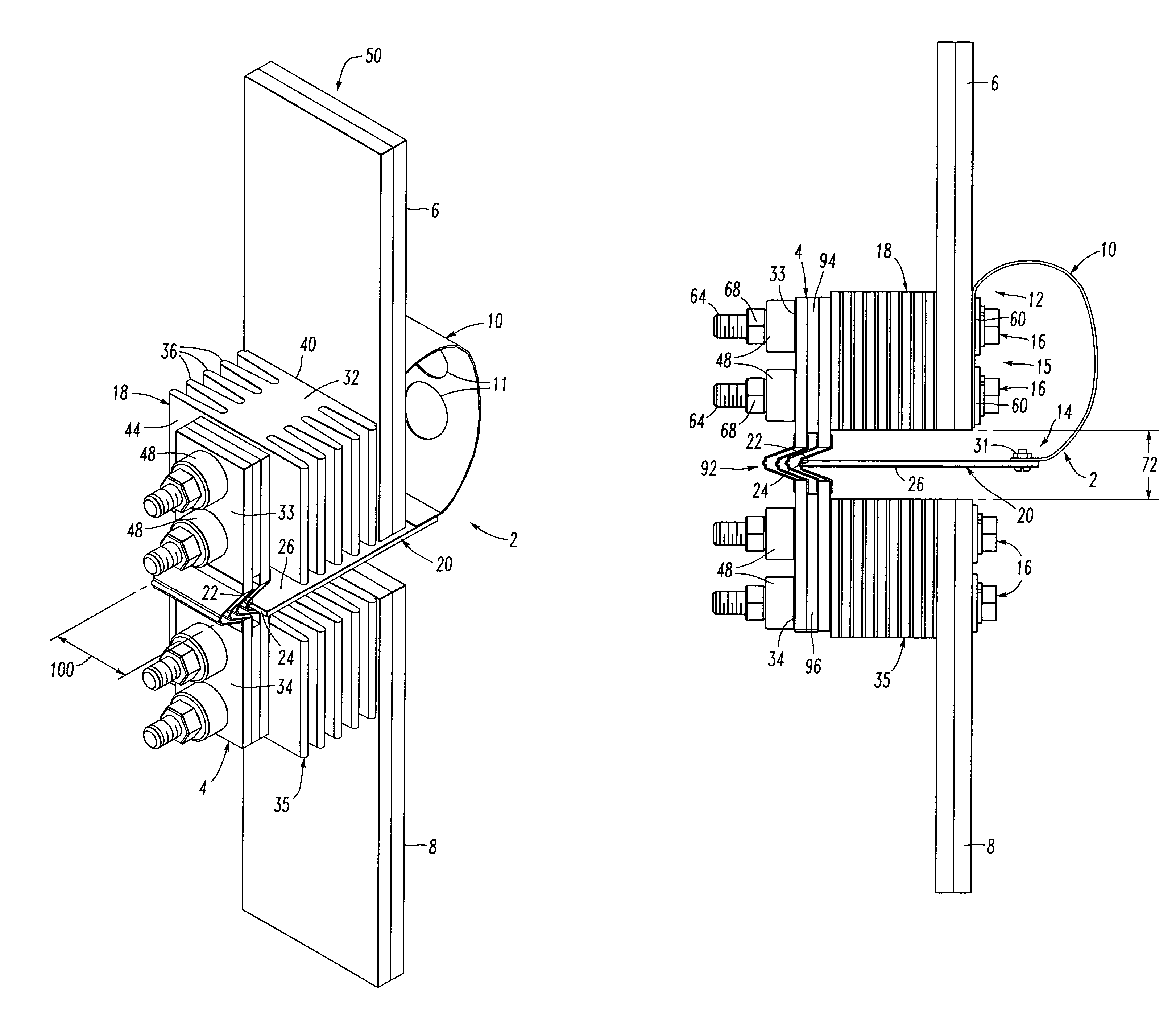
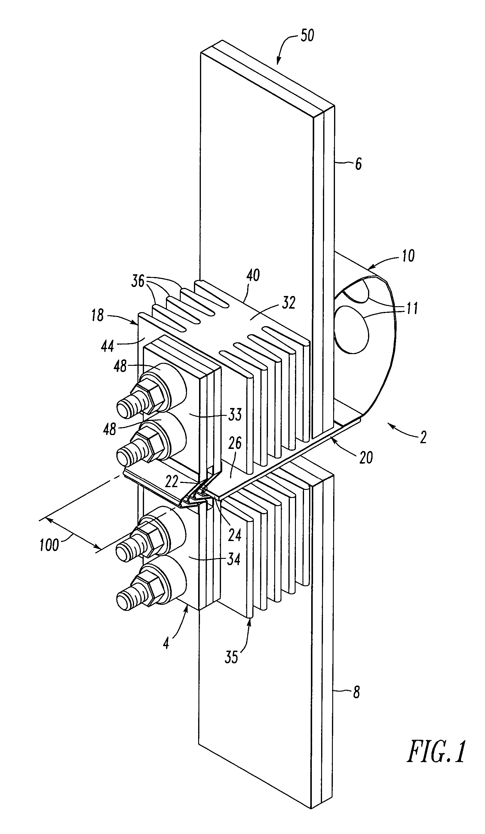
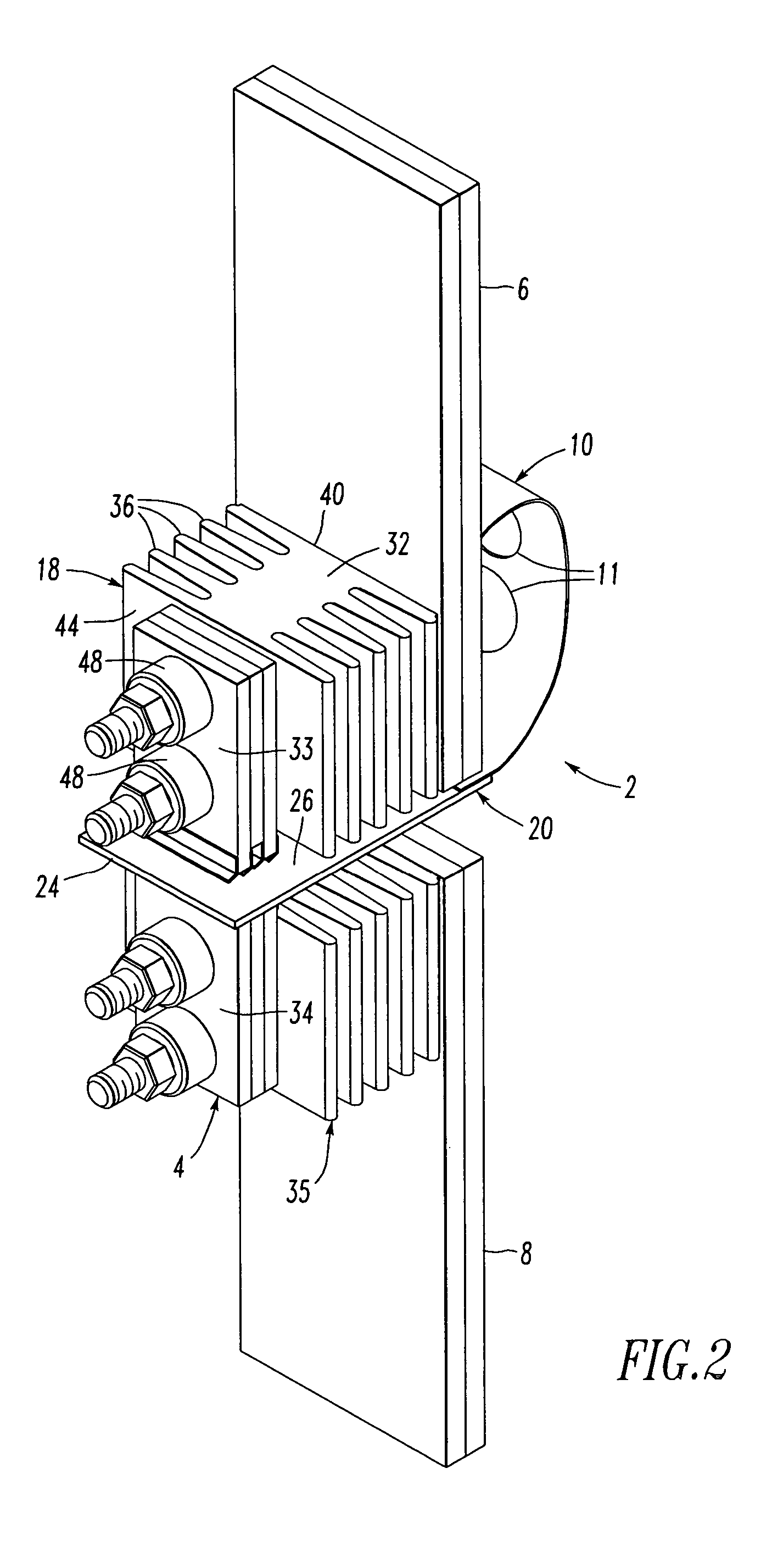
[0028]Referring to FIGS. 1 and 3, a fuse barrier 2 is for a fuse 4 electrically connected between a first low voltage power bus 6 and a second low voltage power bus 8. The fuse 4 has a non-interrupted state (as shown in FIGS. 1 and 3) and...
PUM
 Abstract
Description
Claims
Application Information