Dual-band antenna with easily and finely adjustable resonant frequency, and method for adjusting resonant frequency

a dual-band antenna and fine adjustment technology, applied in the direction of resonant antennas, independent non-interacting antenna combinations, differential interacting antenna combinations, etc., can solve the problem that the current flowing in the main portion of the first radiation conductor plate that is positioned at the top surface of the insulating base cannot be extremely changed, and achieves easy adjustment, high operation efficiency, and increased assembly strength of the first radiation conductor plate

Inactive Publication Date: 2006-02-07
ALPS ALPINE CO LTD
View PDF4 Cites 34 Cited by
  • Summary
  • Abstract
  • Description
  • Claims
  • Application Information

AI Technical Summary

Benefits of technology

[0010]In one aspect, a dual-band antenna includes a support board having a ground conductor. An insulating base is formed on the support board. A first radiation conductor plate covers an opening end of the insulating base and resonates at a first frequency. A feed conductor plate has a first end connected with the first radiation conductor plate and a second end connected with a feed circuit. A short-circuiting conductor plate has a first end connected with the first radiation conductor plate and a second end connected with the ground conductor. A second radiation conductor plate is disposed in an internal space of the insulating base and is connected with the second end of the feed conductor plate such that the second radiation conductor plate resonates at a second frequency higher than the first frequency. The first radiation conductor plate has a bending flap that is bent from the opening end towards a side wall of the insulating base. The bending flap has a cutaway portion that reduces the current path length and / or a cutout portion that increases the current path length.
[0011]In the dual-band antenna, the bending flap of the first radiation conductor plate is engaged with the side wall of the insulating base, and the first radiation conductor plate for the low band is positioned at the opening end of the insulating base. When the first radiation conductor plate is excited, a current flows in the bending flap. The bending flap has a cutaway portion at a corner that reduces the current path length, thereby increasing the resonant frequency. The bending flap has a cutout portion that causes the current to flow around this portion to increase the current path length, thereby reducing the resonant frequency. Removal of a portion of the bending flap using a tool such as a router does not affect the second radiation conductor plate for the high band. Moreover, the distribution of the current flowing in the main portion of the first radiation conductor plate that is positioned at the top surface of the insulating base cannot extremely change. Thus, even if the cutting amount or position is deviated to some extent, such a deviation does not cause a large change in the resonant frequency. Therefore, the resonant frequency for the low band is easily adjustable, and the operation efficiency greatly increases.

Problems solved by technology

Moreover, the distribution of the current flowing in the main portion of the first radiation conductor plate that is positioned at the top surface of the insulating base cannot extremely change.

Method used


Image

  • Dual-band antenna with easily and finely adjustable resonant frequency, and method for adjusting resonant frequency
  • Dual-band antenna with easily and finely adjustable resonant frequency, and method for adjusting resonant frequency
  • Dual-band antenna with easily and finely adjustable resonant frequency, and method for adjusting resonant frequency

Examples


Embodiment Construction

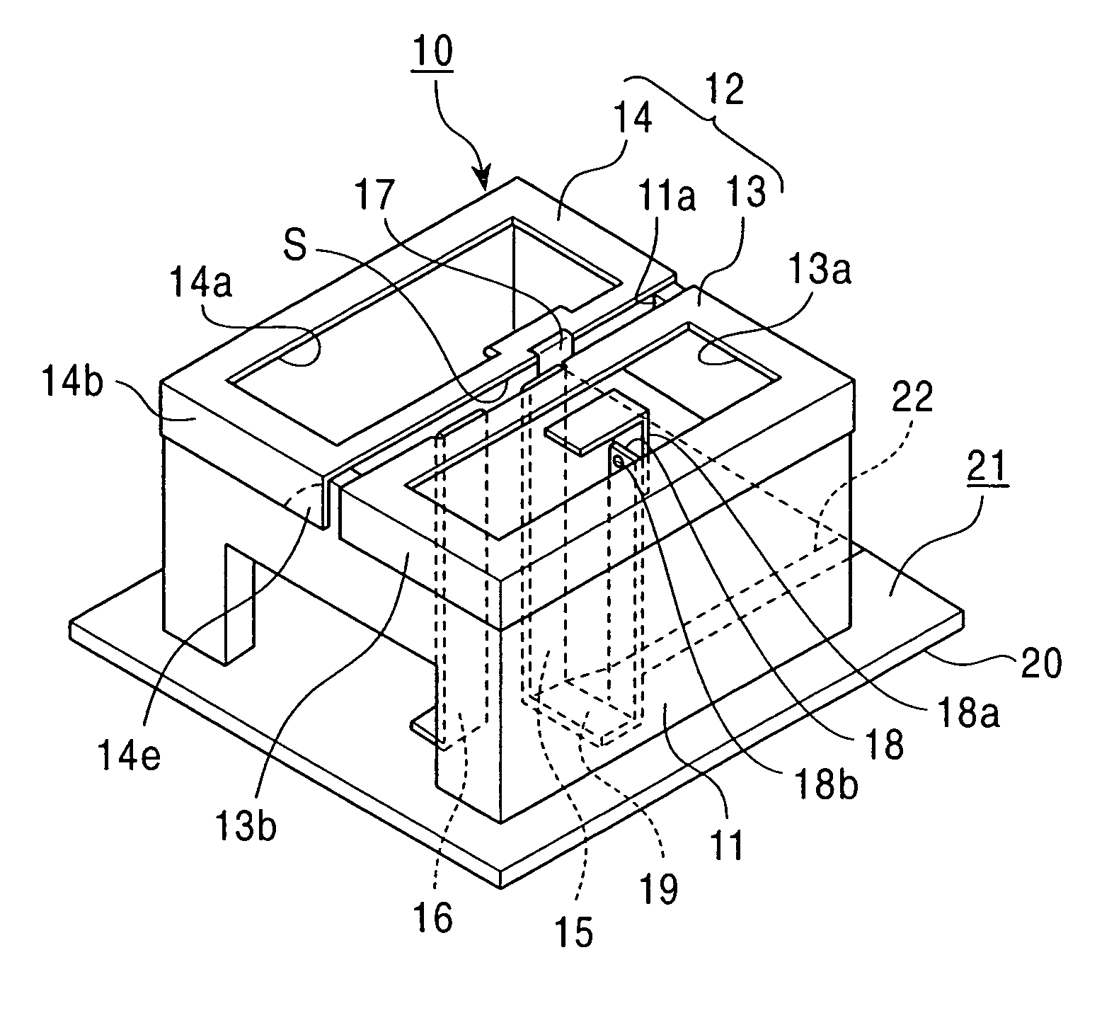
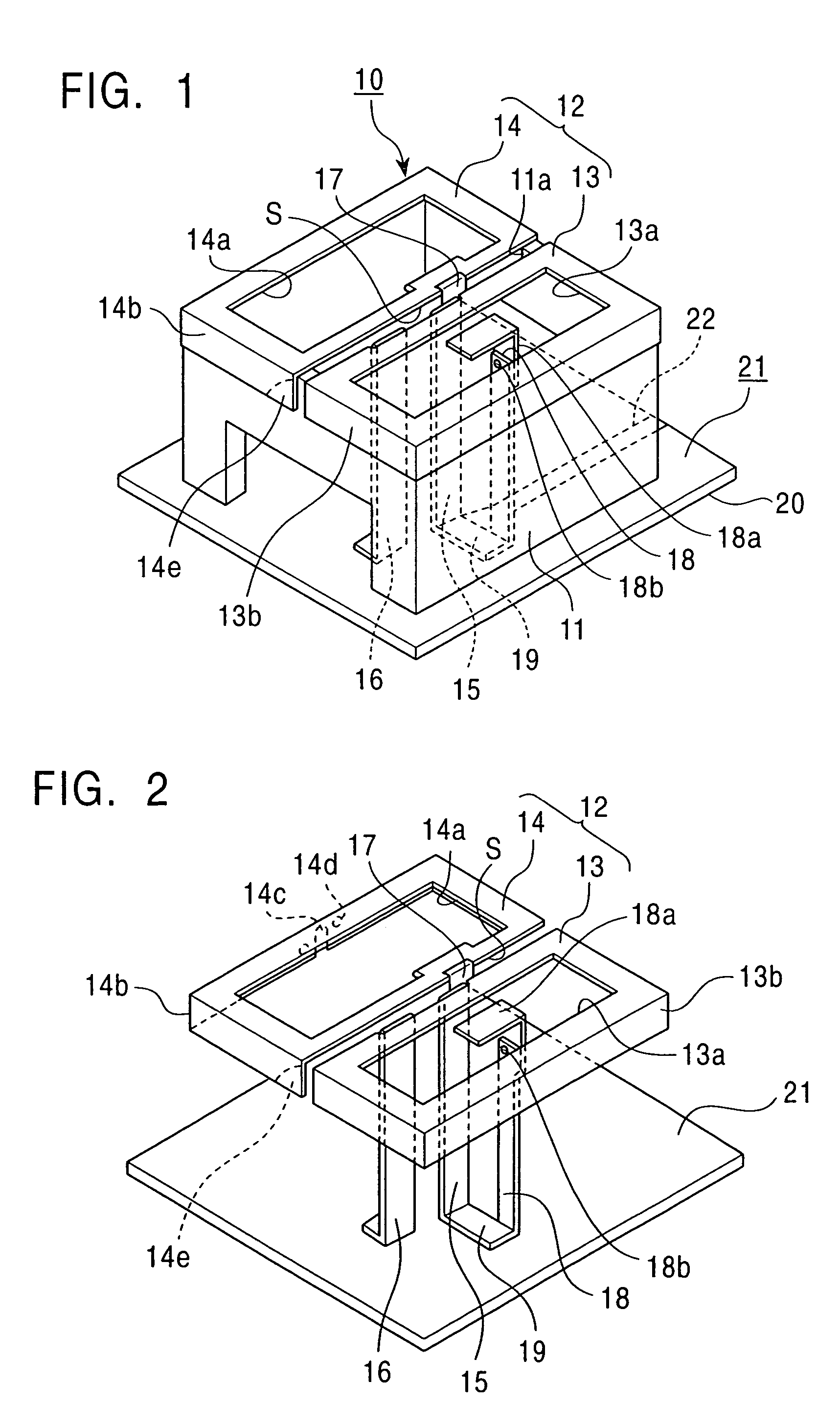
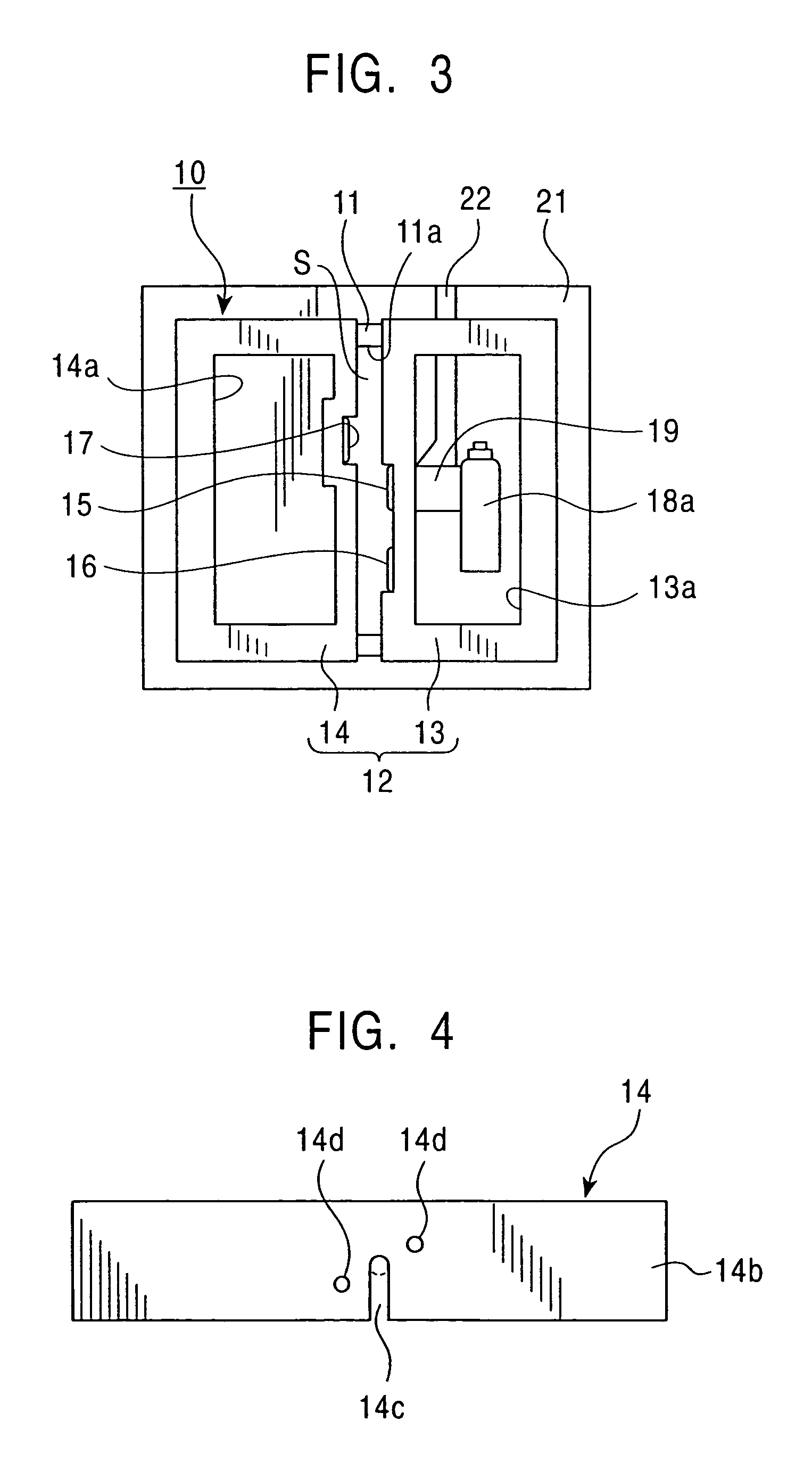
[0025]A dual-band antenna 10 according to an embodiment of the present invention will be described with reference to the drawings. FIG. 1 is a perspective view of the dual-band antenna 10, FIG. 2 is a perspective view for showing conductor plates of the antenna 10 with an insulating base removed, and FIG. 3 is a plan view of the antenna 10. FIG. 4 is an enlarged view of the main portion showing a frequency adjusting portion of the antenna 10, and FIG. 5 is a characteristic chart showing the return loss of the antenna 10 with respect to frequency.

[0026]The dual-band antenna 10 is a compact antenna device, used as an on-vehicle antenna, for example. The dual-band antenna 10 is capable of selectively transmitting and receiving signal waves in a low band (e.g., the 800-MHz AMPS band) and a high band (e.g., the 1.9-GHz PCS band).

[0027]The dual-band antenna 10 includes a support board 21 having a ground conductor 20 on the entirety of a surface opposite to the side of the dual-band antenn...


PUM


Abstract

In a dual-band antenna, an insulating base is formed on a support board having a ground conductor. A first radiation conductor plate for a low band has first and second divided conductor plates for covering an opening end of the insulating base. A feed conductor plate and a first short-circuiting conductor plate are continuously formed with the first divided conductor plates. A second short-circuiting conductor plate is continuously formed with the second divided conductor plate. A second radiation conductor plate for a high band is connected with the feed conductor plate. The feed conductor plate and the second short-circuiting conductor plate are electromagnetically coupled. The second divided conductor plate has a bending flap, and the bending flap is engaged with the insulating base. The bending flap has a cutout or cutaway portion for finely adjusting the resonant frequency.

Description

[0001]This application claims the benefit of priority to Japanese Patent Application No.: 2003-314103, filed on Sep. 5, 2003, which is incorporated herein by reference.BACKGROUND OF THE INVENTION[0002]1. Field of the Invention[0003]The present invention relates to compact dual-band antennas and to a method for adjusting the resonant frequency thereof. More particularly, the present invention relates to a dual-band antenna for use in on-vehicle communication devices, capable of transmitting and receiving signal waves in two frequency bands, and to a method for adjusting the resonant frequency of the dual-band antenna.[0004]2. Description of the Related Art[0005]An inverted-F antenna has been used for resonance in two frequencies. One type of known dual-band inverted-F antenna has a radiation conductor plate with a cutout portion that allows for resonance at two frequencies, i.e., high and low frequencies. Such an antenna is shown in, for example, Japanese Unexamined Patent Applicatio...

Claims


Application Information

Patent Timeline
Patent Type & Authority Patents(United States)
IPC IPC(8): H01Q1/24H01Q13/08H01Q1/38H01Q5/10H01Q9/04H01Q9/30H01Q9/40H01Q21/28H01Q21/29H01Q21/30
CPCH01Q9/0421H01Q9/0442H01Q21/30H01Q21/28H01Q21/29H01Q9/30
Inventor SHIKATA, MASARU
Owner ALPS ALPINE CO LTD
Why Eureka
Try Eureka