Method of ionizing a liquid propellant and an electric thruster implementing such a method

a technology of liquid propellant and electric thruster, which is applied in the direction of machine/engine, marine propulsion, vessel construction, etc., can solve the problems of jet eventually becoming unstable, separating into charged droplets, and affecting the stability of the j

Inactive Publication Date: 2006-02-14
THE BOEING CO
View PDF12 Cites 32 Cited by
  • Summary
  • Abstract
  • Description
  • Claims
  • Application Information

AI Technical Summary

Problems solved by technology

A strong electrostatic field is applied at the needle tip opening and causes an imbalance of surface force due to the accumulation of charges on the surface of the emitted liquid.
As the jet travels away from the Taylor cone, the jet eventually becomes unstable and separates into a spray of charged droplets.

Method used


Image

  • Method of ionizing a liquid propellant and an electric thruster implementing such a method
  • Method of ionizing a liquid propellant and an electric thruster implementing such a method
  • Method of ionizing a liquid propellant and an electric thruster implementing such a method

Examples


Embodiment Construction

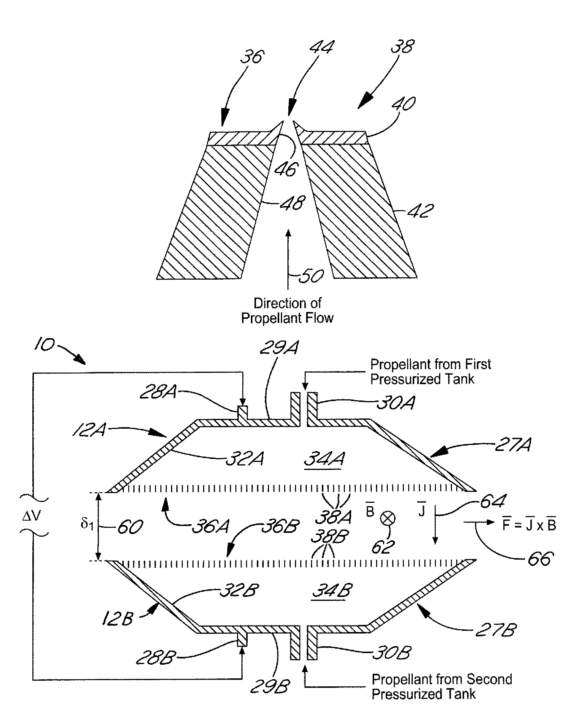
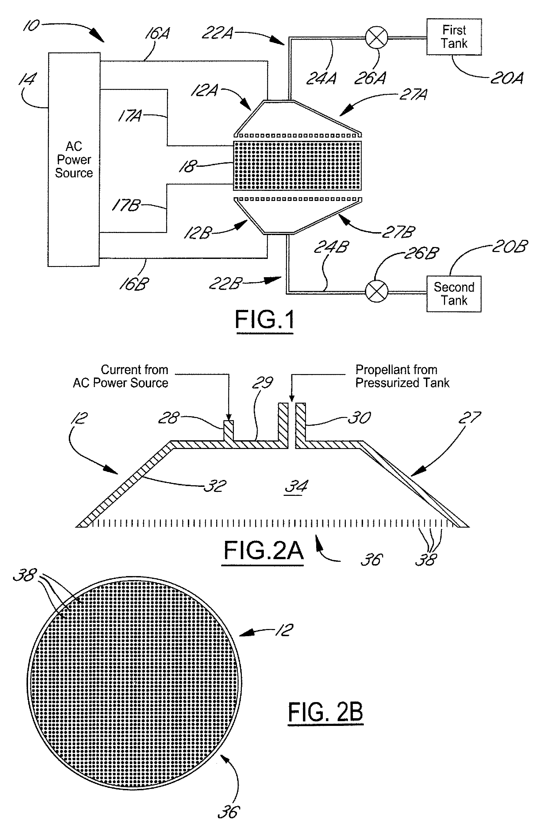
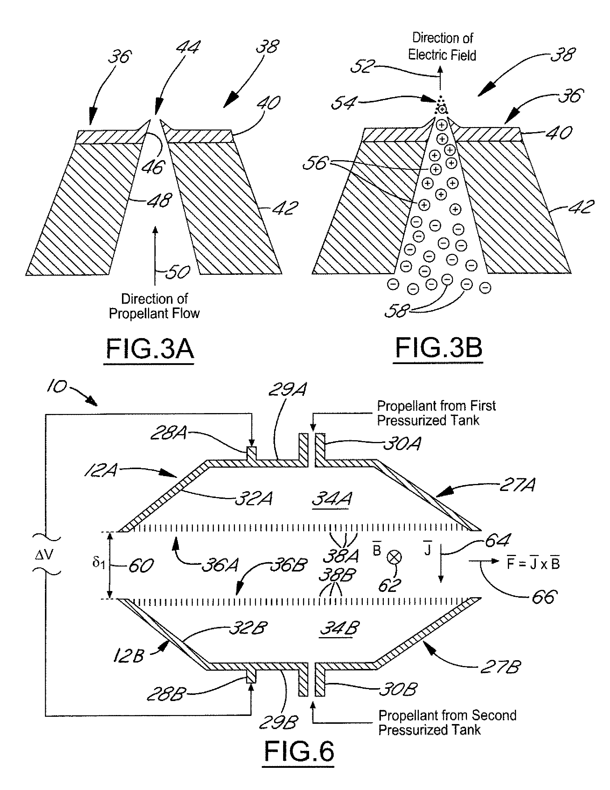
[0026]FIG. 1 is a system diagram of an electromagnetic thruster 10 useful for positioning and translating a spacecraft in space. As shown in the diagram, the electromagnetic thruster 10 primarily includes two showerheads 12A and 12B, a power source 14, a magnetic field generator 18, two tanks 20A and 20B, and two conduit-and-valve systems 22A and 22B.

[0027]The two showerheads 12A and 12B largely comprise electrically conductive material. As shown in FIGS. 1 and 6, the two showerheads 12A and 12B are arranged such that they at least partially face each other and cooperatively define a gap (δ1) 60. Within such a configuration, the two showerheads 12A and 12B primarily serve as emitters for dispensing amounts of ionized propellant (i.e., plasma) into the gap 60. For this reason, the two showerheads 12A and 12B are frequently referred to as “plasma shower-heads.”

[0028]The power source 14, as shown in FIGS. 1 and 6, is electrically interconnected between the two showerheads 12A and 12B v...


PUM


Abstract

A method of ionizing a liquid propellant is disclosed herein. The method includes the steps of applying an electrical charge to a showerhead, delivering a liquid propellant under pressure into a chamber defined within the showerhead, and emitting the liquid propellant under pressure through a plurality of micro-nozzles interspaced within the face of the showerhead to create a plurality of jets that collectively produce an electrospray having charged particles. An electric thruster that implements such a method is also disclosed herein. The thruster includes a showerhead having an inlet and a plurality of micro-nozzles, a reservoir for supplying propellant to the showerhead via the inlet, means for accelerating charged particles, and a power source connected to the showerhead and the accelerating means. The propellant is emitted under pressure from the micro-nozzles to produce an electrospray having charged particles. The charged particles are accelerated by the accelerating means to produce thrust.

Description

BACKGROUND OF INVENTION[0001]The present invention generally relates to propulsion systems for use onboard spacecraft. The present invention more particularly relates to electric thrusters for positioning and translating such spacecraft in space.[0002]Prior to embarking on a space mission, a spacecraft must be equipped with enough propulsion capability to travel through and maneuver within space in order to carry out the mission. To help provide sufficient propulsion, engineers often include thrusters incorporating electric propulsion systems onboard spacecraft, for electric propulsion systems have been shown to produce exhaust velocities of about 10 to 20 kilometers per second (km / s), or even higher. In producing such high exhaust velocities, the amount of propellant required onboard a spacecraft for a given mission is significantly reduced.[0003]Electric propulsion systems generally fall into three main categories. These categories include electrothermal propulsion systems, electr...

Claims


Application Information

Patent Timeline
Patent Type & Authority Patents(United States)
IPC IPC(8): F03H5/00F03H99/00F03H1/00H05H1/00H05H1/54
CPCB05B5/008H05H1/54F03H1/0012B05B5/0255B05B1/14B05B5/1608
Inventor SONG, WEIDONG
Owner THE BOEING CO
Why Eureka
Try Eureka