Expansion reservoir for a master cylinder of a hydraulic force transmission system

a technology of hydraulic force transmission system and expansion reservoir, which is applied in the direction of mechanical equipment, couplings, braking systems, etc., can solve the problems of no longer guaranteed problem-free pressure compensation between the inner chamber of the fluid reservoir and the atmosphere, and the effect of reducing the risk of damag

Inactive Publication Date: 2006-02-14
FTE AUTOMOTIVE GMBH & CO KG
View PDF8 Cites 12 Cited by
  • Summary
  • Abstract
  • Description
  • Claims
  • Application Information

AI Technical Summary

Benefits of technology

[0014]Due to this extremely simple, low-cost configuration of the expansion reservoir, the hydraulic force transmission system filled with hydraulic fluid may, when fitted in the motor vehicle, be rotated together with the motor vehicle by 180° on a rotary stand, without the risk arising of the volume of air left in the fluid chamber, which remains substantially constant irrespective of the state of actuation of the hydraulic force transmission system as a result of combining a flexible reservoir top with a substantially liquid-tight but air-permeable connection to the atmosphere, or some of this volume of air passing via the master cylinder into the hydraulic force transmission system. In the event of rotation of the expansion reservoir, the volume of air left in the fluid chamber of the expansion reservoir namely travels along the reservoir walls to the reservoir bottom in accordance with physical principles and cannot pass from there to the master cylinder via the hydraulic connection because the extension of the hydraulic connection protrudes in defined manner into the fluid chamber and thus prevents this from happening. Instead, the volume of air left in the fluid chamber of the expansion reservoir is trapped or collected completely in the predetermined volume defined in the fluid chamber by the extension of the hydraulic connection.
[0026]Finally, it is possible, in principle, for the expansion reservoir to be constructed in one piece with a housing of the master cylinder. However, it is preferable for the expansion reservoir to be constructed separately from the housing of the master cylinder, wherein the expansion reservoir may be plugged together directly with the master cylinder or be connected with the master cylinder by means of a hose, thereby ensuring greater flexibility with regard to the possible fitting points of the expansion reservoir.

Problems solved by technology

Fluctuations in the volume of hydraulic fluid, to be compensated by the expansion reservoir, may occur here for example in the case of rapid clutching sequences for the clutch engaging or disengaging process, in particular in the case of automated clutch operation, or be caused by clutch wear or temperature variations in the system.
There is then a risk that the air deliberately left in the inner chamber of the fluid reservoir will migrate via the connection to the hydraulic system into the main brake cylinder or clutch master cylinder, thereby impairing functioning when the hydraulic system is operated.
A further problem consists in the fact that the concertina-like bellows in the fluid reservoir may possibly dip into the brake or hydraulic fluid contained in the fluid reservoir if the hydraulic system is actuated very quickly and the filling level of the fluid reservoir therefore changes rapidly.
There is a degree of probability that the gas-permeable membrane or the valve with the closable slot on the concertina-like bellows will then become wet with the brake or hydraulic fluid in such a way that problem-free pressure compensation between the inner chamber of the fluid reservoir and the atmosphere is no longer guaranteed.
This too may impair functioning when the hydraulic system is in operation.

Method used


Image

  • Expansion reservoir for a master cylinder of a hydraulic force transmission system
  • Expansion reservoir for a master cylinder of a hydraulic force transmission system
  • Expansion reservoir for a master cylinder of a hydraulic force transmission system

Examples


Embodiment Construction

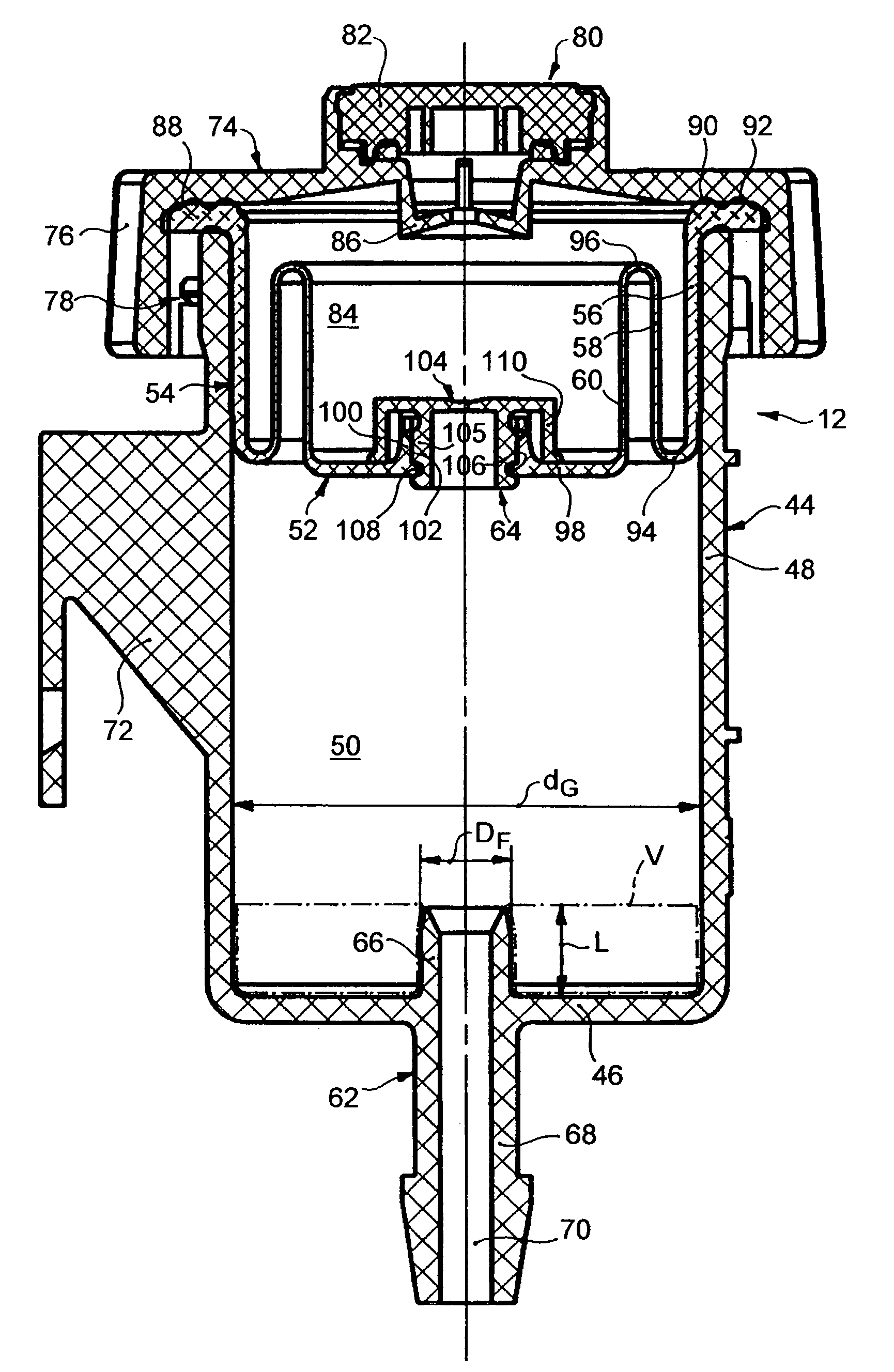
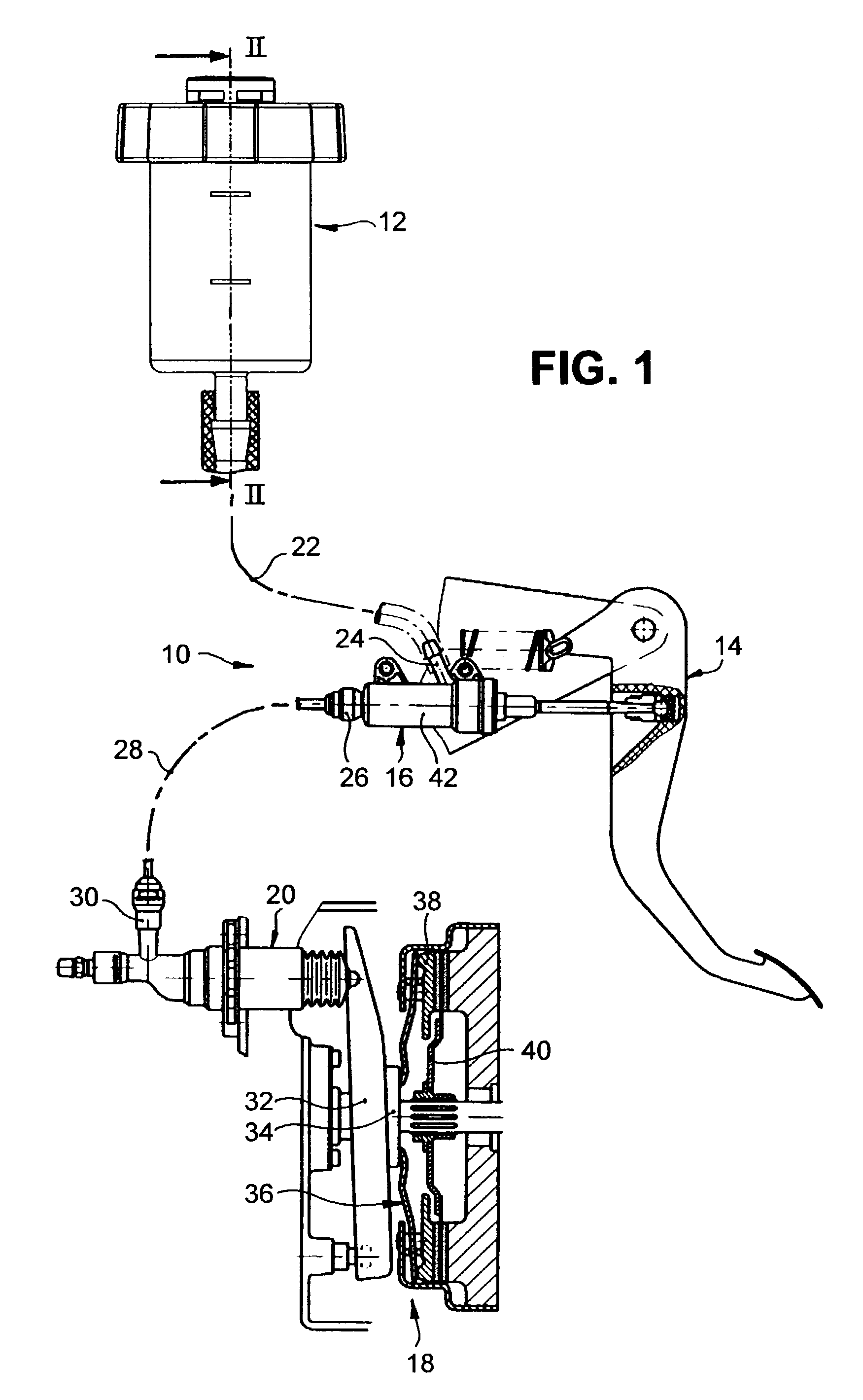
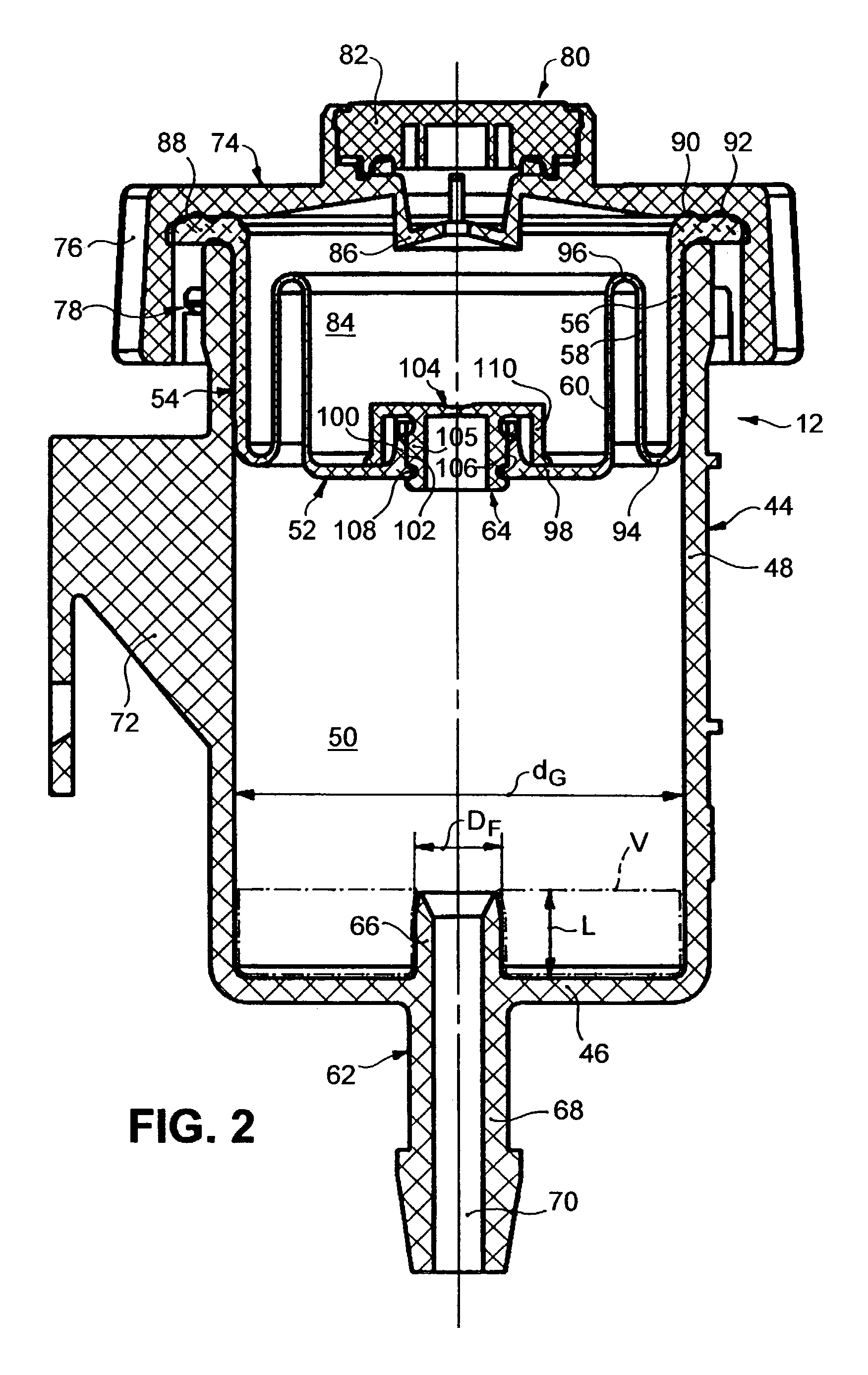
[0030]FIG. 1 shows a hydraulic clutch control for a motor vehicle, designated overall as 10, as an example of a hydraulic force transmission system, whose hydraulic part comprises an expansion or compensating reservoir 12 filled with hydraulic fluid and described in more detail below with reference to FIG. 2, a clutch master cylinder 16 actively connected with a clutch pedal 14 and a clutch slave cylinder 20 actively connected with a clutch 18. The expansion reservoir 12 is connected by means of a hydraulic hose 22 to an expansion and pressure compensating connection 24 of the clutch master cylinder 16, whose pressure connection 26 is connected by means of a hydraulic line 28 to a pressure connection 30 of the clutch slave cylinder 20. All the components illustrated in FIG. 1, except for the expansion reservoir 12, are known per se and are therefore described only insofar as seems necessary for an understanding of the present invention.

[0031]With regard to the per se known functioni...


PUM


Abstract

An expansion reservoir is disclosed, which has a fluid chamber defined by a reservoir bottom and a flexible reservoir top movable relative to the reservoir bottom as a function of the reservoir filling level, wherein a hydraulic connection to a master cylinder is provided at the reservoir bottom while the reservoir top comprises a substantially liquid-tight but air-permeable connection to the atmosphere, in order to allow pressure compensation between an air volume left in the filled fluid chamber and the atmosphere. The hydraulic connection to the master cylinder comprises an extension protruding into the fluid chamber, which extension defines a predetermined volume V in the fluid chamber which is larger than the air volume left in the filled fluid chamber. In addition thereto, the reservoir top may take the form of a rolling lobe bellows, which comprises a plurality of wall portions substantially concentric at least in the undeformed state.

Description

BACKGROUND OF THE INVENTION[0001]The present invention relates to an expansion reservoir for a master cylinder of a hydraulic force transmission system. In particular, the invention relates to an expansion reservoir for a master cylinder of a hydraulic clutch control or brake system, as used in huge numbers in the automotive industry.DESCRIPTION OF THE PRIOR ART[0002]In a hydraulic brake system, the main brake cylinder constitutes the master cylinder, with which the expansion or compensating reservoir serving as a storage chamber for the brake fluid is so connected that, when the main brake cylinder is in the unactuated state, a fluid exchange may take place both with the primary or pressure chamber thereof via a pressure compensating port and with the secondary or expansion chamber, separated from the pressure chamber by means of the so-called primary lip seal, via an expansion port but, in the actuated state, only with the expansion chamber, after the primary lip seal has travelle...

Claims


Application Information

Patent Timeline
Patent Type & Authority Patents(United States)
IPC IPC(8): F15B1/26B60T11/16B60T11/22B60T11/26B60T17/06
CPCB60T11/16B60T17/06B60T11/26
Inventor BORNKESSEL, DIETHARDLEUSCHKE, RAINERSCOTT, ELLIOTT
Owner FTE AUTOMOTIVE GMBH & CO KG
Why Eureka
Try Eureka