Method for fixation of optical fiber in optical device module, and fixation pipe

Inactive Publication Date: 2006-02-14
SUMITOMO OSAKA CEMENT CO LTD
View PDF7 Cites 4 Cited by
  • Summary
  • Abstract
  • Description
  • Claims
  • Application Information

AI Technical Summary

Benefits of technology

[0028]In accordance with the invention related to claim 7, since the fixation pipe is electrified by the copper bit and the solder is fused by Joule heat generated from said electrifying, the solder itself dose not become high temperature, and operators are at low risk, such as of hurting themselves by mistake. Als

Problems solved by technology

Likewise, as to the fixation of the optical fiber by the solder in a case, due to the sticking fixation pipe 8 inside the case, it is impossible to locate the optical modulator 1 that is an optical element, and the side plate of the case 11 closer to each other than the fixed distance and it makes it difficult to miniaturize the optical device module.
In addition, the coated part 6 consisti

Method used


Image

  • Method for fixation of optical fiber in optical device module, and fixation pipe
  • Method for fixation of optical fiber in optical device module, and fixation pipe
  • Method for fixation of optical fiber in optical device module, and fixation pipe

Examples


Embodiment Construction

[0051]The favorable examples of the present invention will be explained in detail hereinafter.

[0052]Although the following embodiments exemplify an optical modulator as optical element, it goes without saying that, beyond the optical modulator, the present invention can be applied to the modulation of various optical elements, such as light source like semiconductor laser, and photo detector.

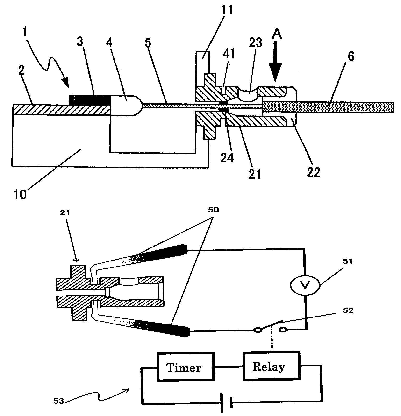
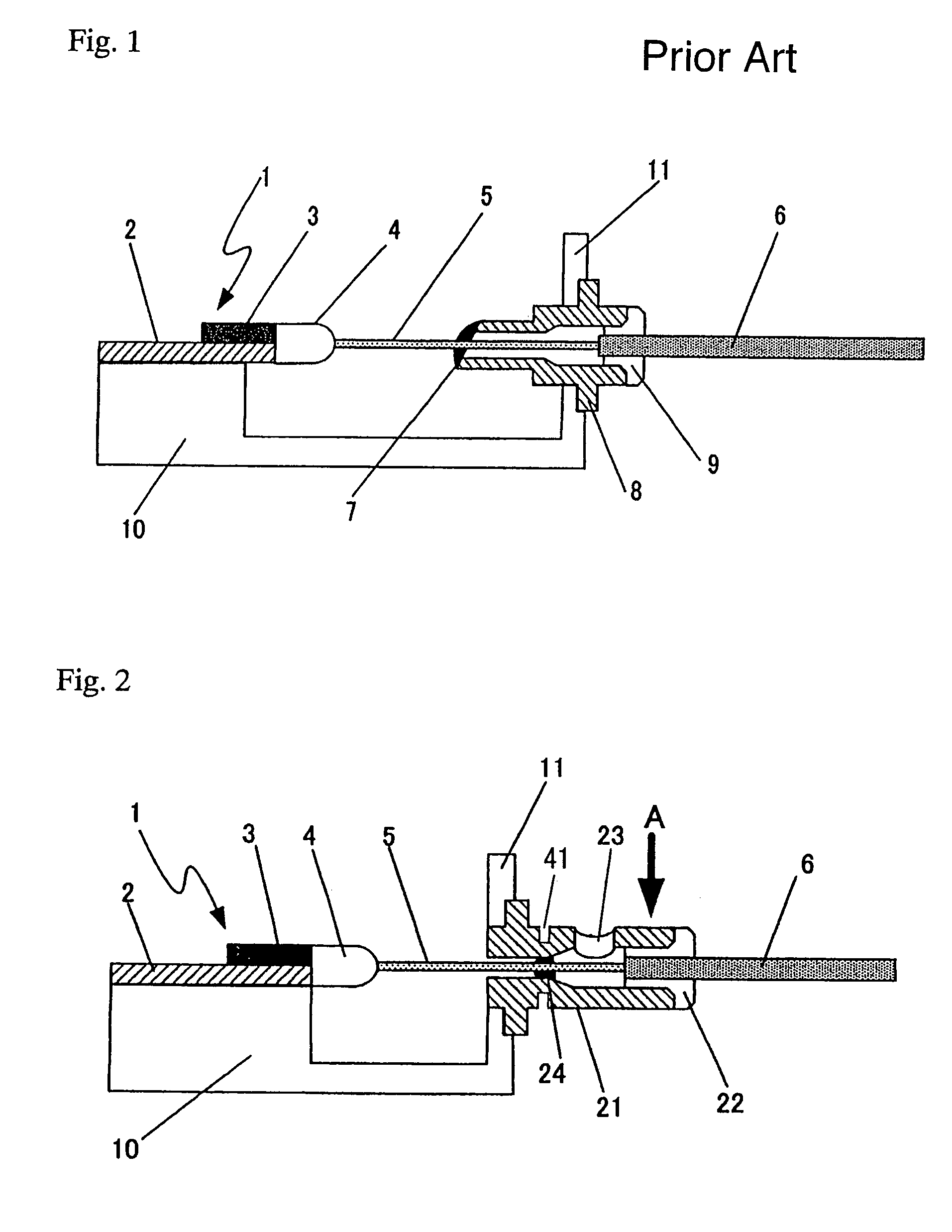
[0053]FIG. 2 is the section view of the optical modulator module applying the present invention, and as in FIG. 1, it explains the structure related to the optical modulator 1 and the optical fiber 5 adjacent to the side plate 11 of the case 10. As to the member that is also used in FIG. 1, same reference letters are attached to in FIG. 2.

[0054]As described in FIG. 2, the fixation pipe 21 is fixed in the side plate of the case 11, and the optical fiber 5 is inherent placed inside said fixation pipe.

[0055]In the intermediate part of the fixation pipe (it is not necessary to be set up exactly in t...


PUM


Abstract

A method for fixation of optical fiber in an optical device module, and a fixation pipe, the method of fixation comprising the steps of utilizing a fixation pipe configured for insertion of the optical fiber, and adapted for affixation of the fiber by solder in an intermediate part of the pipe, the external surface of the intermediate part having a groove for a copper bit; installing the pipe to the case so that the intermediate part is positioned outside the case; inserting the fiber inside the pipe so that a stripped part of the fiber is in the intermediate part, and a coated part of the fiber is positioned opposite to the case from the intermediate part; and contacting a copper bit to the groove, to affix the fiber to the pipe by solder. The fixation pipe has the features described above.

Description

BACKGROUND OF THE INVENTION[0001](1) Field of the Invention[0002]The present invention relates to a method for fixation of optical fiber in an optical device module and a fixation pipe. In particular, it relates to a method and a fixation pipe for fixation of optical fiber in an optical device module, which has the narrowed interior space between an optical modulator, which is an optical element, and the case incorporating it, such as an optical modulator module.[0003](2) Related Art Statement[0004]Corresponding to the increasing demand for recent high-speed and high-capacity information communication, dense wavelength division multiplexing (DWDM) of optical networking has been adopted more and more. Accordingly it is necessary to utilize a multitude of optical elements, such as an optical modulator, by combining them. Particularly it is required to prevent expansion of the whole equipment by miniaturizing each part of the optical device module that incorporates these optical elemen...

Claims


Application Information

Patent Timeline
IPC IPC(8): G02B6/26G02B6/42
CPCG02B6/4238G02B6/4248
Inventor SAITOU, TSUTOMUSHINOZAKI, MINORUSUGAMATA, TOORU
Owner SUMITOMO OSAKA CEMENT CO LTD
Why Eureka
Try Eureka