End mill having different axial rake angles and different radial rake angles

Active Publication Date: 2006-02-14
OSG
View PDF9 Cites 82 Cited by
  • Summary
  • Abstract
  • Description
  • Claims
  • Application Information

AI Technical Summary

Benefits of technology

[0006]It is therefore an object of the present invention to provide an end mill which is capable of exhibiting a sufficiently high degree of durability even in its use for cutting a tough work material,

Problems solved by technology

However, even the end mill as disclosed in JP-Y2-2557189 is not capable of exhibiting a sufficiently high degree of durability when it is used for cutting a tough work material such as a heat resistant alloy (e.g., kovar, inconel and stainless steel).
Since such a tough work material inherently ten

Method used


Image

  • End mill having different axial rake angles and different radial rake angles
  • End mill having different axial rake angles and different radial rake angles
  • End mill having different axial rake angles and different radial rake angles

Examples


Example

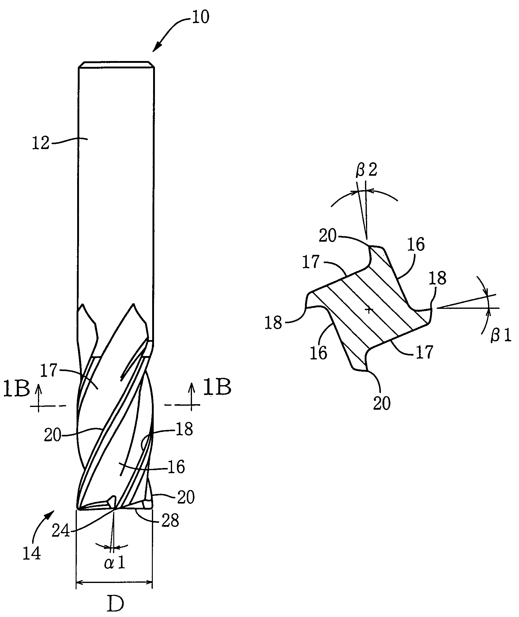
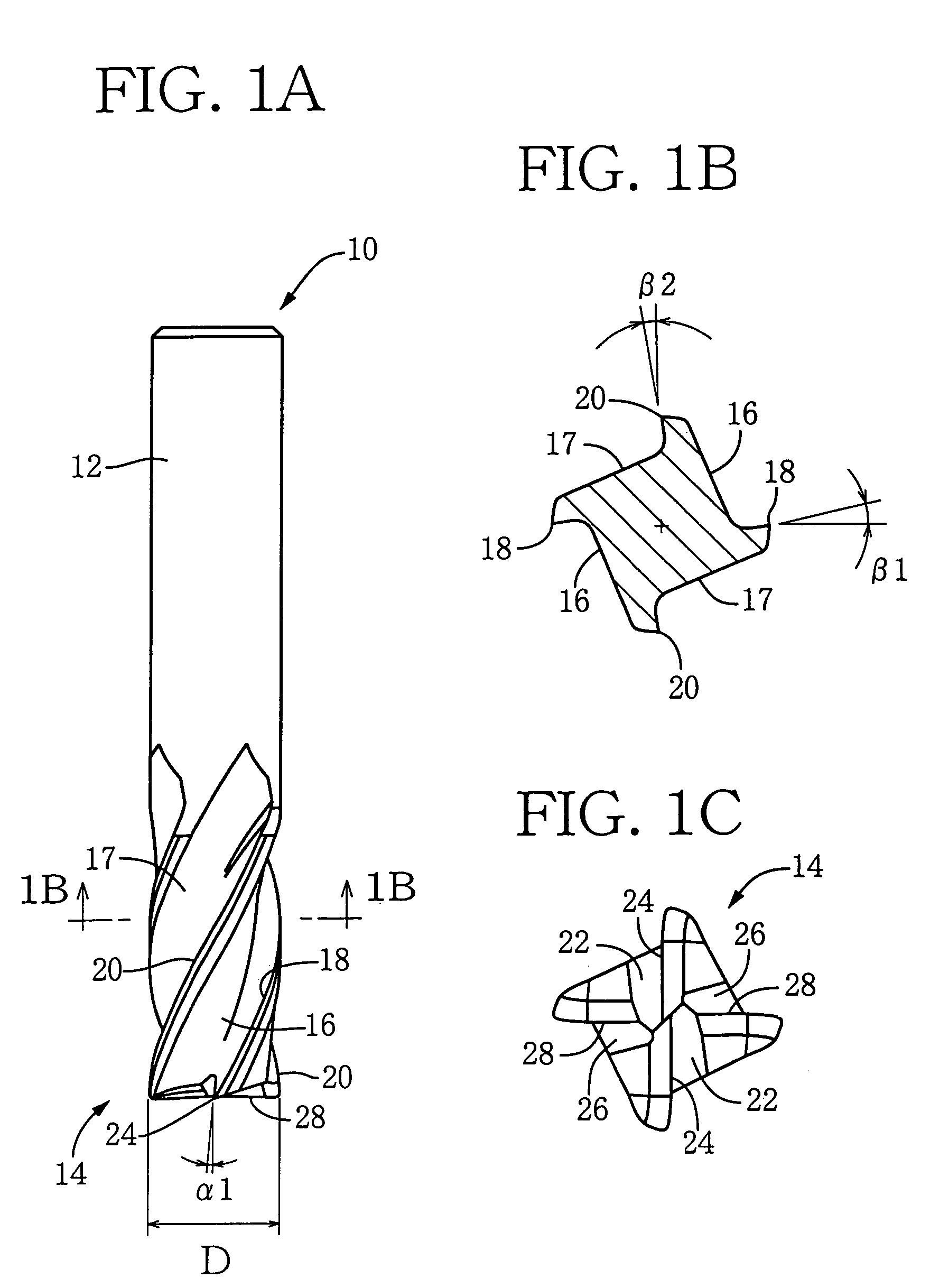
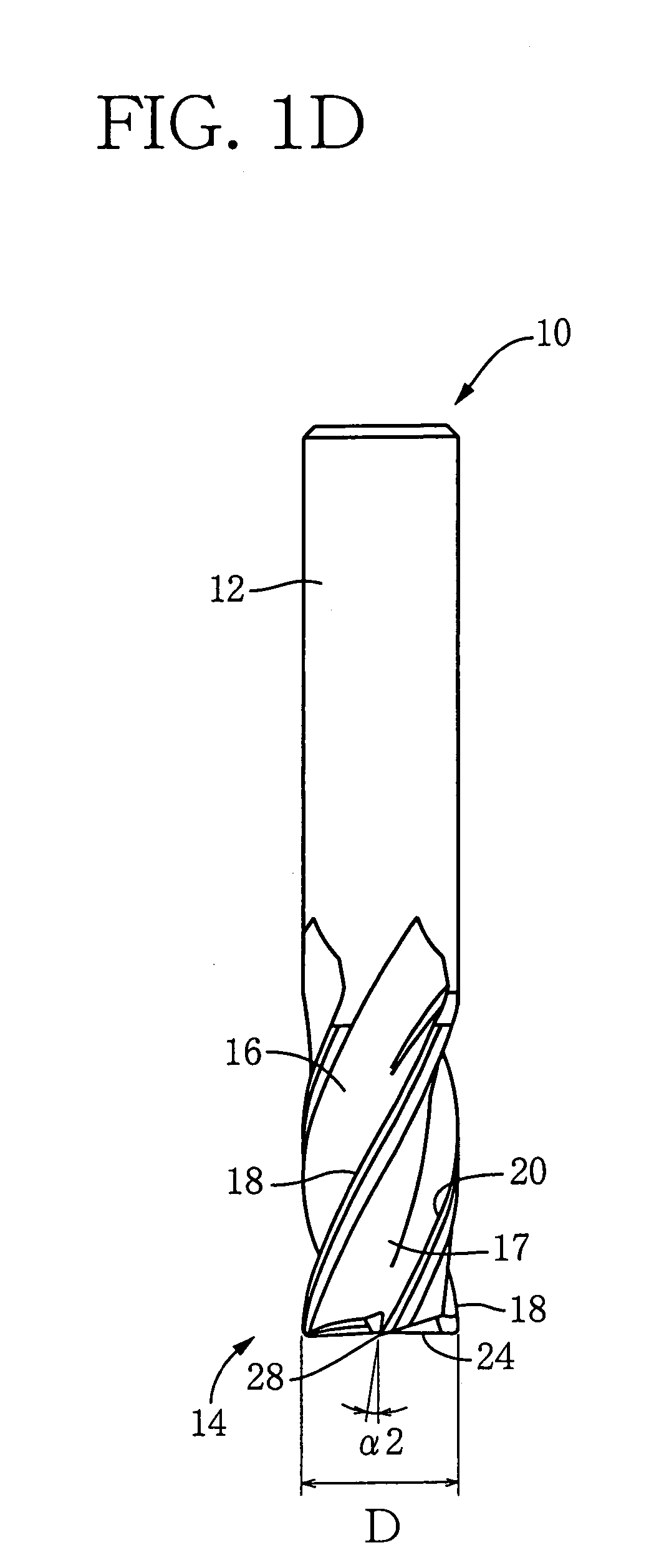
[0038]Referring first to FIGS. 1A–1D, there will be described a four-flute square end mill 10 which is constructed according to an embodiment of this invention. FIG. 1A is a front elevational view of the end mill 10. FIG. 1B is a cross sectional view taken along line 1B—1B of FIG. 1A. FIG. 1C is a bottom view of the end mill 10. FIG. 1D is a side elevational view of the end mill 10, in other words, a front elevational view of the end mill 10 as rotated by 90° about its axis from its angular position of FIG. 1A. This end mill 10 is provided by a cylindrical body made of a cemented carbide. The cylindrical body has a shank portion 12 and a fluted portion 14 which are coaxial with each other. Four helical flutes 16, 17 are formed in an outer circumferential surface of the fluted portion 14 such that the four helical flutes 16 are located around the axis and are equi-angularly spaced apart from each other at an angular interval of 90°. Four peripheral cutting edges 18, 20 are formed alo...


PUM


Abstract

An end mill including a cylindrical body having (a) flutes each formed in the cylindrical body and each extending from an axially distal end of the cylindrical body toward an axially proximal end of the cylindrical body, (b) peripheral cutting edges each provided by one of widthwise opposite edges of a corresponding one of the flutes, and (c) end cutting edges each located at the axially distal end of the cylindrical body and contiguous to a corresponding one of the peripheral cutting edges. The end cutting edges include first and second end cutting edges, while the peripheral cutting edges include first and second peripheral cutting edges which are contiguous to the first and second end cutting edges, respectively. A first axial rake angle of the first end cutting edge is smaller than a second axial rake angle of the second end cutting edge, while a first radial rake angle of the first peripheral cutting edge is larger than a second radial rake angle of the second peripheral cutting edge.

Description

BACKGROUND OF THE INVENTION[0001]1. Field of the Invention[0002]The present invention relates in general to an end mill, and more particularly to such an end mill capable of exhibiting an excellent durability even in its use for cutting a tough work material, for example, a heat resistant alloy such as kovar, inconel and stainless steel.[0003]2. Discussion of the Related Art[0004]There is known a square end mill including a cylindrical body made of a cemented carbide and having (a) a plurality of flutes, (b) a plurality of peripheral cutting edges which are provided by the respective flutes, and (c) a plurality of end cutting edges which are located at the axially distal end of the cylindrical body and are contiguous to the respective peripheral cutting edges. As an example of such a square end mill, JP-Y2-2557189 (publication of Japanese Utility Model issued in 1997) discloses an end mill in which one of the plurality of peripheral cutting edges has a radial rake angle smaller than...

Claims


Application Information

Patent Timeline
IPC IPC(8): B26D1/12B23C5/10
CPCB23C5/10Y10T407/1962Y10T407/1946B23C2210/0407B23C2210/0414
Inventor KAWAI, RYOGOOSAWA, JIRO
Owner OSG
Why Eureka
Try Eureka