Vehicular transmission

a technology of transmission and vehicle, applied in the field of transmission, can solve the problems of serious shock, impair the driving experience or the comfort of the user's vehicle, and achieve the effect of smooth in-gear operation

Inactive Publication Date: 2006-02-14
HONDA MOTOR CO LTD
View PDF7 Cites 32 Cited by
  • Summary
  • Abstract
  • Description
  • Claims
  • Application Information

AI Technical Summary

Benefits of technology

[0006]It is an object of the present invention to provide a vehicular transmission that comprises a continuously variable ratio-change mechanism and a fixed ratio rotational trans

Problems solved by technology

In such a transmission, there is a problem of shock that may be caused from a large torque acting on the drive wheels when the transmission is shifted from its neutral mode to its in-gear mode with the first hydraulic clutch coming into engagement to transmit the rotational driving force of the engine to the drive wheels (i.e., when

Method used


Image

  • Vehicular transmission
  • Vehicular transmission
  • Vehicular transmission

Examples


Embodiment Construction

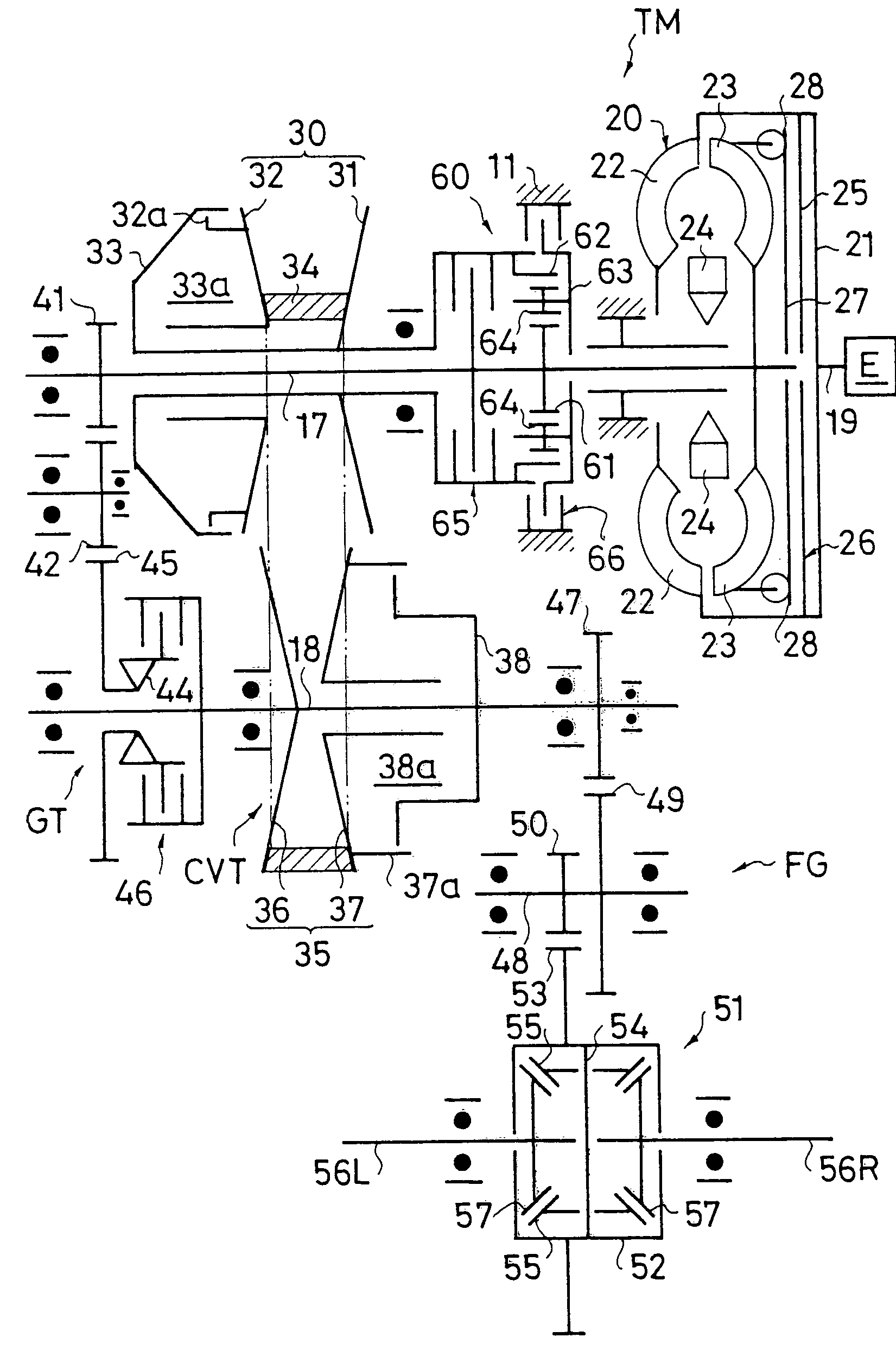
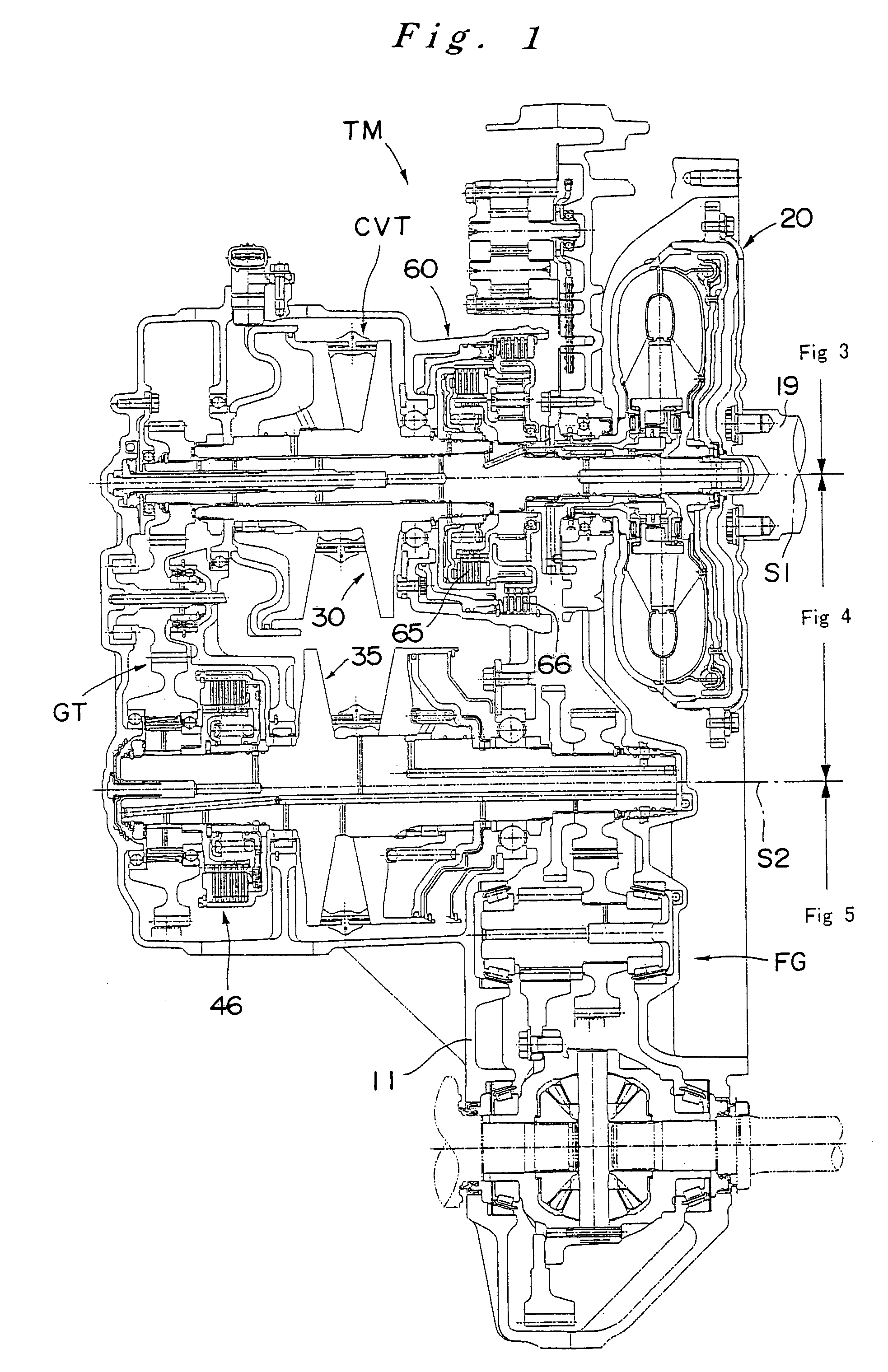
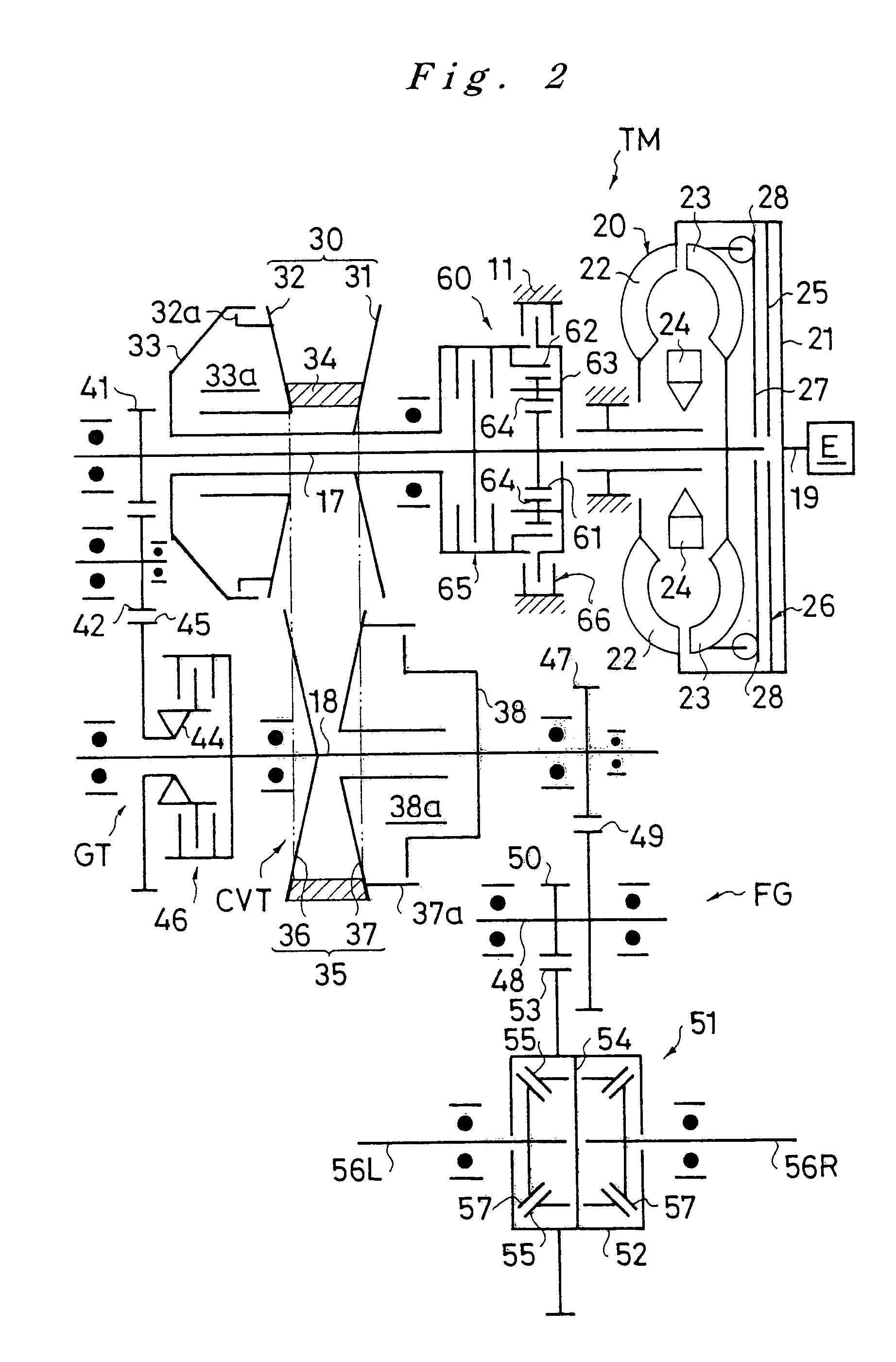
[0020]Now, a preferred embodiment according to the present invention is described in reference to the drawings. FIG. 1˜FIG. 5 show a transmission as a preferred embodiment. FIG. 1 shows the entire construction of the transmission in a cross-sectional view while FIG. 2 shows the construction of the power transmission mechanism of this transmission. FIG. 3˜FIG. 5 show in enlargement the sections of the transmission shown in FIG. 1, those sections being located, respectively, above the center S1 of the main shaft 17 of the transmission, between the center S1 of the main shaft 17 and the center S2 of the countershaft 18 of the transmission and below the center S2 of the countershaft 18.

[0021]The transmission TM comprises a ratio-change mechanism in a casing 11, which is assembled of a converter case 12, a center case 14, a left case 15 and a cover 16. The main shaft 17 and the countershaft 18, which extend in parallel with each other, are supported rotatably by bearings in the casing 11...


PUM


Abstract

A transmission equipped with a continuously variable ratio-change mechanism CVT and a LOW rotational transmission mechanism GT, which are disposed parallel with each other, comprises a forward clutch 65 and a reverse brake 66, which are used to set a power transmission through the continuously variable ratio-change mechanism, a LOW clutch 46, which is used to set a power transmission through the LOW rotational transmission mechanism, and a control unit ECU and a hydraulic control valve HV, which control the engagement of the clutches and the brake. When the transmission is switched from its neutral mode to its in-gear mode, at first, the forward clutch 65 is brought gradually into engagement, and then it is released before the LOW clutch 46 is brought into engagement in a squat control.

Description

FIELD OF THE INVENTION[0001]The present invention relates to a transmission equipped with a continuously variable ratio-change mechanism and a fixed ratio rotational transmission mechanism, which are disposed in parallel with each other between the input shaft and the output shaft of the transmission.BACKGROUND OF THE INVENTION[0002]Such a vehicular transmission, which comprises a continuously variable ratio-change mechanism and a fixed ratio rotational transmission mechanism (a rotational transmission mechanism comprising a gear train) arranged in parallel with each other, has been known (for example, refer to Japanese Patent Publication No. S63(1988)-14228 and to Japanese Laid-Open Patent Publication No. 2002-48213). For example, Japanese Patent Publication No. S63(1988)-14228 discloses a transmission that comprises a belt-type continuously variable ratio-change mechanism and a reduction gear train (a gear-type rotational transmission mechanism or a fixed ratio rotational transmis...

Claims


Application Information

Patent Timeline
IPC IPC(8): F16H37/02F16H37/00F16H61/04F16H61/08F16H61/662
CPCF16H37/021F16H61/66259F16H2061/023F16H2061/0448Y10T477/689F16H2312/02Y10T74/19019Y10T477/6237Y10T477/6217F16H2061/0488
Inventor KANDA, TOMOYUKISATO, TAKAOTSUBATA, YOSHIMICHI
Owner HONDA MOTOR CO LTD
Why Eureka
Try Eureka