Heatsink apparatus

a technology of heat sink and cooling chamber, which is applied in the direction of electrical apparatus casings/cabinets/drawers, instruments, semiconductor/solid-state device details, etc., can solve the problems of difficult or difficult arrangement of components, and achieve the effect of effective and efficient cooling

Inactive Publication Date: 2006-02-14
ORACLE INT CORP
View PDF13 Cites 53 Cited by
  • Summary
  • Abstract
  • Description
  • Claims
  • Application Information

AI Technical Summary

Benefits of technology

[0004]A first aspect of the present invention may provide a computing apparatus. The computing apparatus has first and second computing elements and a heatsink thermally coupled to each of the first and second computing elements. A portion of the heatsink thermally coupled to the first computing element is thermally separated from a portion of the heatsink thermally coupled to the second computing element by a region having a reduced thermal conductivity. This arrangement provides a simple and efficient system whereby each of two primary heat sources within a computing system may be provided with effective cooling.
[0006]A second aspect of the invention may provide a computing apparatus including a housing that defines a cavity. The computer apparatus further includes within the cavity multiple computing elements and a fan for generating airflow to cool said components. The fan has a first path defining an air inflow and a second path defining an air outflow. One of the first and second paths is ducted to a vent facility in a first wall of said housing, and the other one of said first and second paths communicates with said cavity adjacent said first wall. At least two computing elements which are primary heat sources within the cavity are positioned in said first path or said second path, a heatsink is attached to said at least two computing elements and the heatsink is positioned in said first path or said second path. This arrangement provides for effective and efficient cooling of primary heat sources within a computing system by control of the airflow through the computing system to provide cooling to a combined heatsink for the heat sources.

Problems solved by technology

In high density systems it may be impossible or very difficult for components to be arranged so as to provide optimum flow of cooling air to all components of a given system or system module.

Method used


Image

  • Heatsink apparatus
  • Heatsink apparatus
  • Heatsink apparatus

Examples


Embodiment Construction

[0016]Embodiments and examples are described hereafter by way of example only in the following with reference to the accompanying drawings.

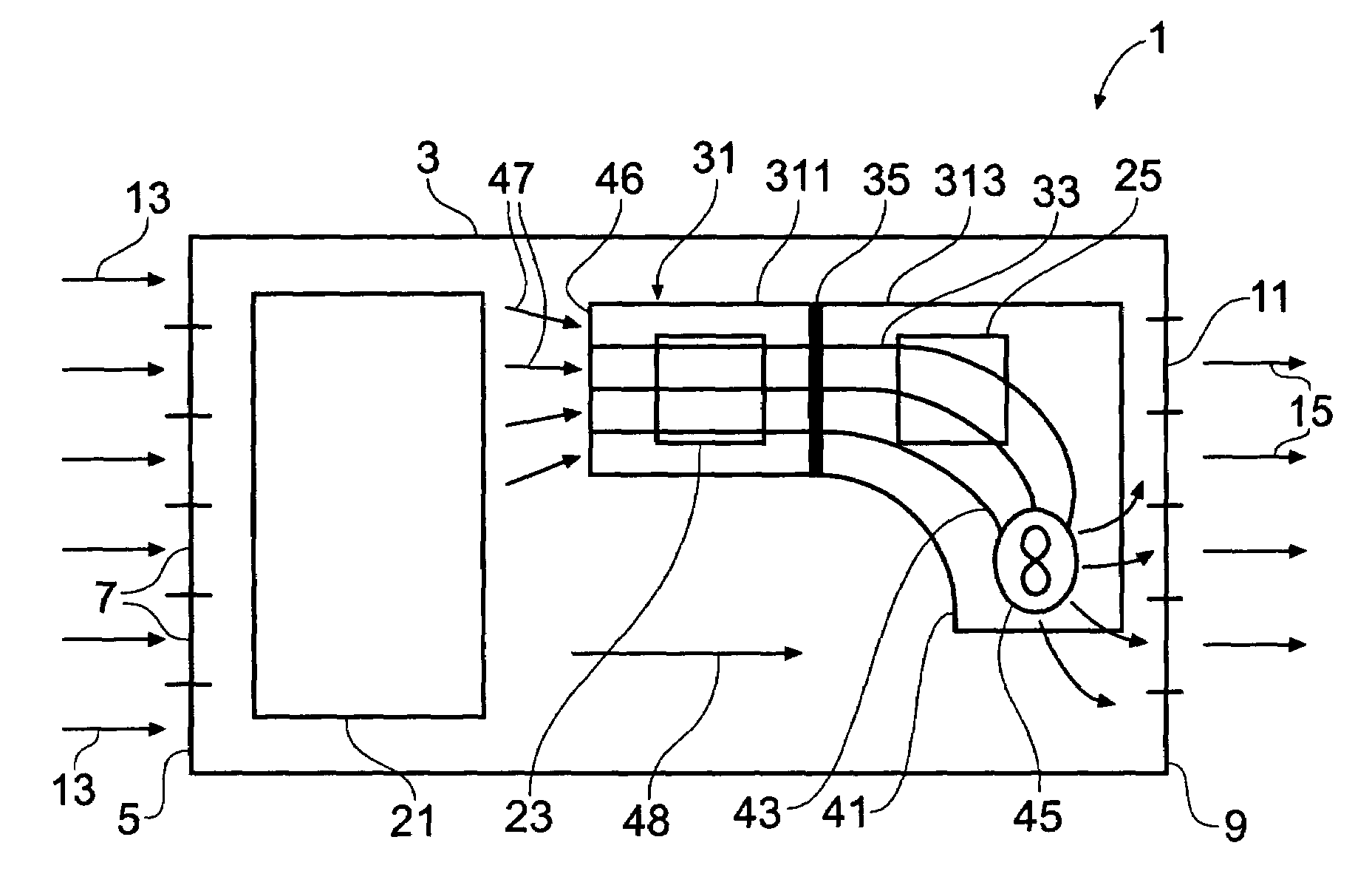
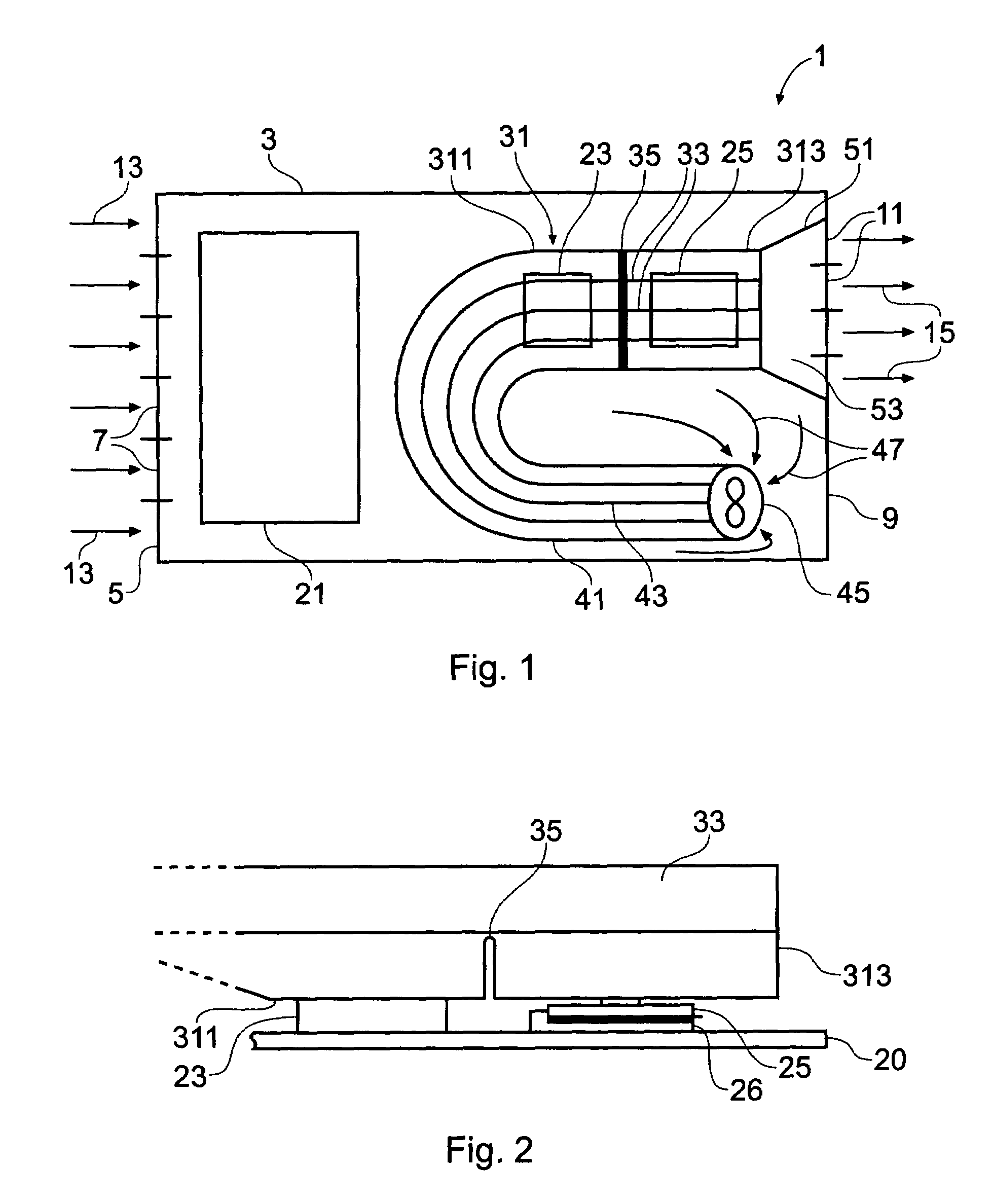
[0017]FIG. 1 shows an example of an air cooled computer system module 1. The computer system module has a housing 3 which has formed through a first face 5 a plurality of air inlet vents 7. The housing 3 also has formed through a second face 9, a plurality of air outlet vents 11. Thus a flow of air for cooling the module 1 enters via the first face 5 through vents 7 (as indicated by arrows 13) and exits via the second face 9 through vents 11 (as indicated by arrows 15). In the present example the air flow is driven in a direction generally from the first face to the second face. This can be achieved by means of an optional intake duct fan 45 and / or by one or more fans external to the computer system module (possibly in another module of the computer system). The intake duct fan(s) and / or the external fan(s) can be supplemented by or replaced by d...


PUM


Abstract

There is provided a computing apparatus. The computing apparatus has first and second computing elements and a heatsink thermally coupled to each of the first and second computing elements. A portion of the heatsink thermally coupled to the first computing element is thermally separated from a portion of the heatsink thermally coupled to the second computing element by a region having a reduced thermal conductivity.

Description

BACKGROUND OF THE INVENTION[0001]The present invention relates to heatsink apparatus, and in particular but not exclusively to ducted heatsink apparatus for computer system components.[0002]One application for the present invention relates to high density computer systems, for example, computer server systems for telecommunications applications. In telecommunications applications, it is important to provide high reliability and high capacity of operation. Various approaches have been taken to providing such high-performance, high reliability systems. Typically such systems are designed around providing redundant resources so that if one component of the system develops a fault, the system remains operational using the redundant resources. Fault tolerance can also be achieved, for example, with multiprocessor systems that provide redundancy through dynamic, e.g., software-controlled, task distribution. High density systems are typically rack mountable, with one or more processor syst...

Claims


Application Information

Patent Timeline
Patent Type & Authority Patents(United States)
IPC IPC(8): G06F1/20H01L23/467
CPCH01L23/467H01L2924/0002H01L2924/00
Inventor GARNETT, PAUL JEFFREYOSBORN, JAY KEVINBURNHAM, ANDREW STEPHEN
Owner ORACLE INT CORP
Why Eureka
Try Eureka