
Disc driving device and wobble information detection method

a driving device and information detection technology, applied in the direction of read-only discs, instruments, recording signal processing, etc., can solve the problems of complex circuit configuration of the wobble signal demodulating circuit, deterioration of the reproduction characteristics of the address, cross-talk components from neighboring turns of the track, etc., to achieve the effect of improving the s/n ratio

Inactive Publication Date: 2006-02-14
KONINKLIJKE PHILIPS ELECTRONICS NV +2
View PDF10 Cites 26 Cited by
  • Summary
  • Abstract
  • Description
  • Claims
  • Application Information

AI Technical Summary

Benefits of technology

[0005]It is therefore an object of the present invention to provide a disc driving device and a wobble information detection method in which wobble components can be detected in a simple configuration from a disc-shaped recording medium having the information such as address information formed efficiently into the wobble components and in which the S / N ratio may be improved in reproducing the information contained in the wobble components.

Problems solved by technology

However, with the system of inserting e.g., the address information into the wobble signal, corresponding to the FM modulated carrier signal, a problem is raised that address reproduction characteristics are deteriorated by cross-talk components from neighboring turns of the track.
In the system of inserting e.g., the address information into the wobble signal by PSK modulating the carrier signal, there is raised a problem that harmonics components at phase change points are superimposed on playback signals to deteriorate reproduction characteristics.
Moreover, in the case of the PSK modulation, the harmonics components are contained, with the result that the circuit configuration of the wobble signal demodulating circuit becomes complicated.

Method used


Image

  • Disc driving device and wobble information detection method
  • Disc driving device and wobble information detection method
  • Disc driving device and wobble information detection method

Examples


Embodiment Construction

[0072]The wobbling system for an optical disc, an optical disc drive for recording and / or reproducing data on or from the optical disc, and a method for producing the optical disc, according to the present invention, are now explained in detail.

1. Wobbling System for Optical Disc

1-1 Overall Explanation of the Wobbling System

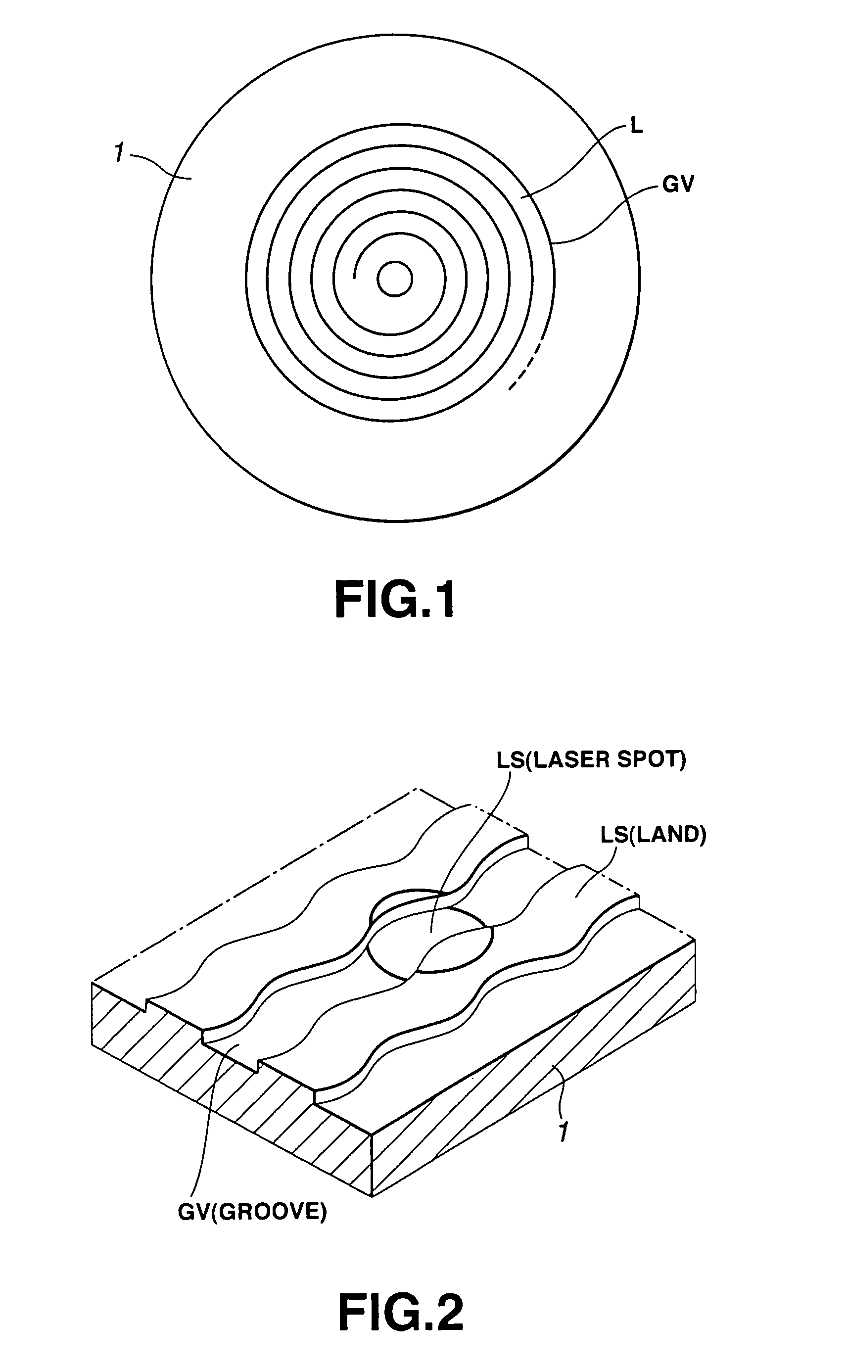
[0073]In an optical disc according to an embodiment of the present invention, a groove GV, operating as a recording track, is formed, as shown in FIG. 1. This groove GV is formed spirally from the inner rim towards the outer rim of the disc. Thus, when seen in a radial cross-section, the optical disc has a convex-shaped land L and a recessed groove GV, in alternation with one another, as shown in FIG. 2.

[0074]The groove GV of the optical disc 1 is formed meandering relative to the tangential direction thereof, as shown in FIG. 2. The meandering shape of the groove GV is in meeting with a wobbling signal. So, with the optical disc drive, both edge positions of the...


PUM

PropertyMeasurementUnit
thicknessaaaaaaaaaa
sizeaaaaaaaaaa
lengthaaaaaaaaaa

Abstract

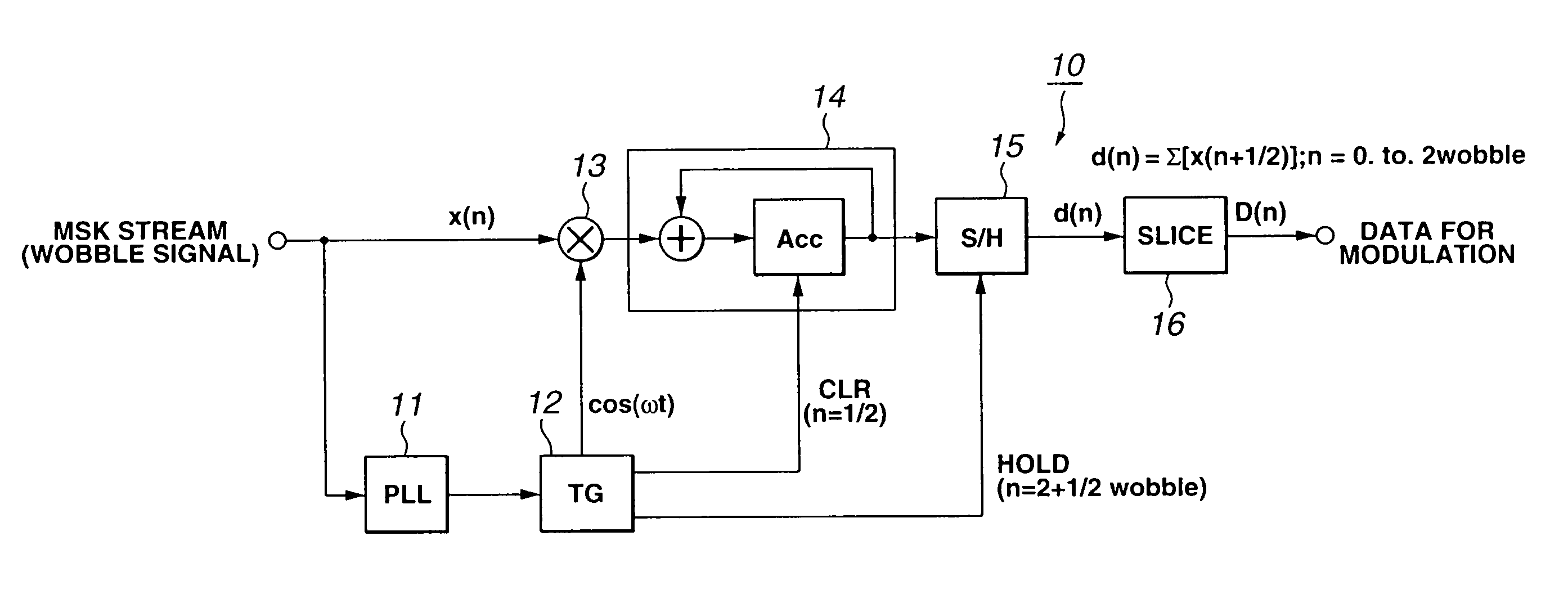
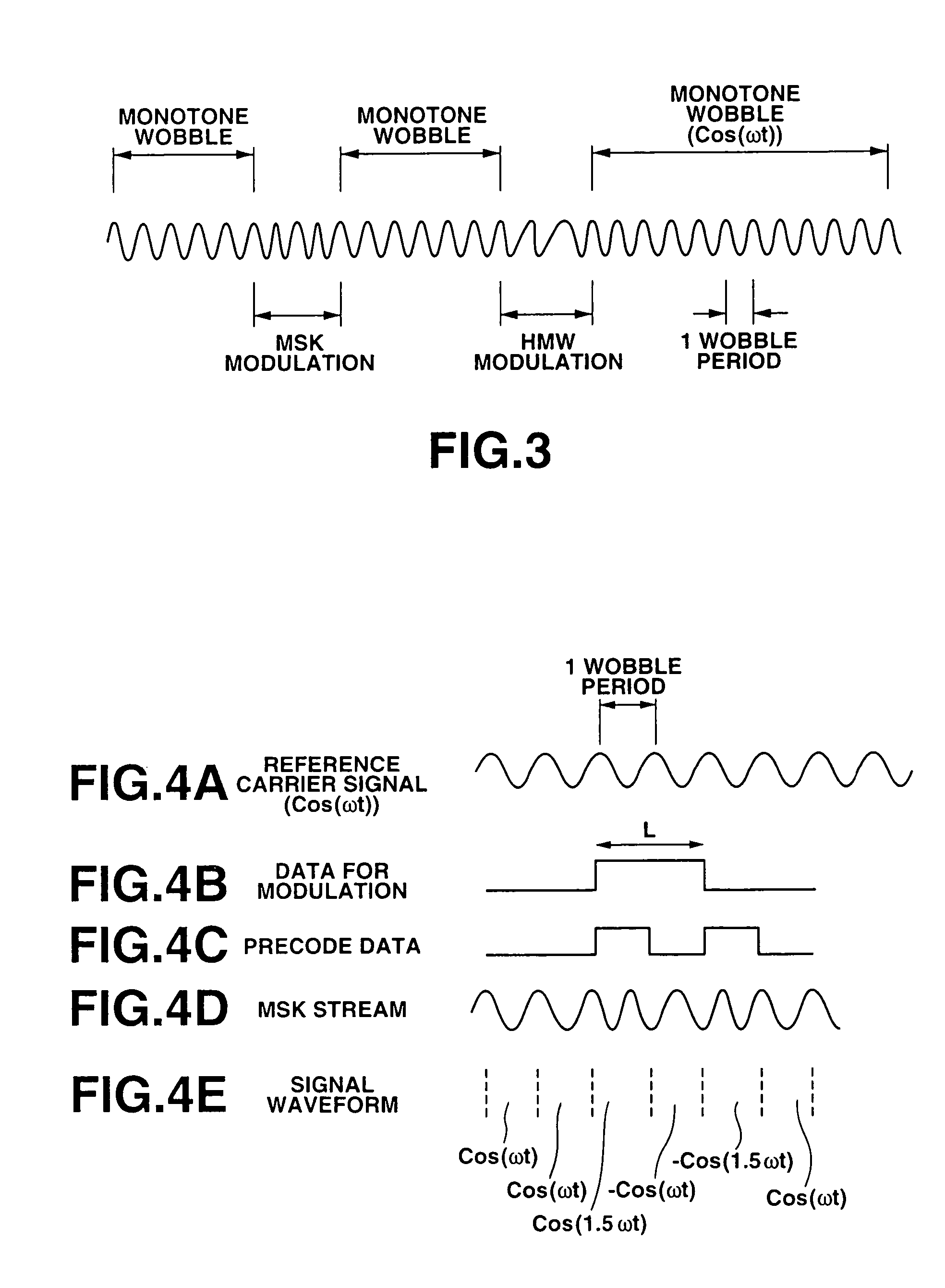
In an optical disc, a wobble signal is to be detected by a simple configuration. In the optical disc, the address information, modulated onto a sinusoidal cannier signal by adding even harmonics signals to the sinusoidal carrier signal and by changing the polarity of the harmonics signals, is formed into the wobble signal. In detecting the wobble signal from the optical disc to demodulate the address information, in a method for detecting the wobble signal, an even harmonics signal and data clocks are generated, and the even harmonics signal so generated are multiplied with the reproduced wobble signal. The resulting product signal is integrated every data clock. The sign of the digital information is verified based on the integrated value at an end edge of the data clock.

Description

BACKGROUND ART[0001]This invention relates to a disc driving device for recording and / or reproducing data for a disc-shaped recording medium, having a land and / or a groove formed thereon in a circling fashion for operating as a recording track formed meandering in meeting with the wobble signal, and to a wobble information detection method for detecting the information formed into the wobble of the recording track of the disc-shaped recording medium.DESCRIPTION OF RELATED ART[0002]Up to now, an optical disc having a guide groove, termed a circling pre-groove, has been known. If this pre-groove is formed, the groove and / or the land (area sandwiched between neighboring turns of the groove) become a recording track. By this pre-groove, formed in the optical disc, the disc driving side, responsible for recording and / or reproduction, is able to detect the components of both edges of the recording track from the reflected laser light to effect servo control in such a manner that the laser...

Claims


Application Information

Patent Timeline
Patent Type & Authority Patents(United States)
IPC IPC(8): G11B7/00G11B20/10G11B7/004G11B7/005G11B7/007G11B20/12G11B20/14G11B27/19G11B27/24G11B27/30
CPCG11B7/005G11B20/1217G11B20/14G11B27/24G11B27/3027G11B7/0053G11B2220/2541G11B7/007G11B7/24082G11B2020/1239G11B2020/1265G11B2020/1268G11B2020/1287G11B2020/1298G11B2220/213G11B2220/216G11B2220/218G11B2220/235
Inventor HEEMSKERK, JACOBUS PETRUS JOSEPHUSSCHEP, CORNELIS MARINUSSTEK, AALBERTTANAKA, SHINICHIFURUMIYA, SHIGERUKOBAYASHI, SHOEIKOBAYASHI, NOBUYOSHI
Owner KONINKLIJKE PHILIPS ELECTRONICS NV
Learn More